Reverse and stop squirrel-cage induction motor
An induction motor is a reversible machine. To change the direction of rotation of the rotor, it is necessary to change the direction of rotation of the magnetic field (by switching the supply wires to the terminals of the two phases of the motor) — Engine start and brake circuits
The mechanical characteristics for two directions of rotation are shown in Fig. 1.
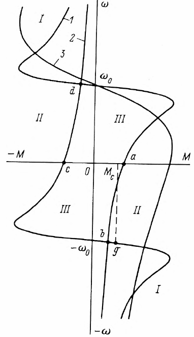
Rice. 1. Family of mechanical characteristics of an induction motor for reversible operation in stop mode with energy supply to the network (I), opposition mode (II) and motor (III) 1, 2 — natural; 3 — artificial.
A squirrel cage induction motor can be used not only as a motor but also as a brake. In stop mode, each electric motor always works as a generator. In this case, an induction electric motor with a squirrel-cage rotor can have three braking modes.
In regenerative braking mode, the machine operates with negative slip. In this case, the speed of the rotor exceeds the speed of rotation of the magnetic field.Of course, to switch to this mode, an external active moment must be applied to the side of the shaft.
The feed-back mode is widely used in lifting installations. During the descent, the propulsion system, due to the potential energy of the load, can acquire a speed exceeding the speed of rotation of the magnetic field, and the descent will occur in an equilibrium state corresponding to a certain point g on the mechanical characteristic, when the static moment created by the descending load, is balanced by the engine braking torque.
In conventional drives with reactive static torque, the mode in question is implemented only by means of special control circuits, which make it possible to reduce the speed of rotation of the magnetic field. The mechanical characteristics of an induction machine for feed-back mode are shown in the same figure. 1.
As shown, the maximum torque in the generator mode is slightly higher than in the motor mode, and the critical slip in absolute value is the same.
Asynchronous generators as such have a very narrow range, namely wind power plants... Since the wind force is not constant and, accordingly, the speed of rotation of the device changes significantly, an asynchronous generator is preferable under these conditions.
The most widely used is the braking mode — opposition. The transition to this mode of asynchronous motors, as well as DC motors, is possible in two cases (Fig. 1): with a significant increase in static torque (section ab) or when switching the stator winding for a different direction of rotation (section cd).
In both cases, the motor operates with a slip greater than 1 until the currents exceed the starting currents. Therefore, for a squirrel-cage motor, this mode can only be used to quickly stop the drive.
When zero speed is reached, the motor must be disconnected from the mains, otherwise it will tend to accelerate in the opposite direction.
When braking by opposed wound rotor motors, a rheostat resistance must be introduced in the rotor circuit to limit the current and increase the braking torque.
It is also possible dynamic braking mode… However, this raises some difficulties. When the motor is disconnected from the mains, the machine's magnetic field also disappears. It is possible to excite an induction machine from a direct current source which is connected to a stator disconnected from the alternating current network. The source should provide a current in the stator winding close to nominal. Since this current is limited only by the electrical resistance of the coil, the DC source voltage must be low (typically 10 — 12 V).
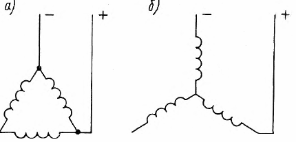
Rice. 2. Connecting the stator of an induction motor to a DC source in dynamic braking mode when connected in delta (a) and star (b)
Self-excitation is also used for dynamic braking. The capacitors are connected to the stator disconnected from the mains.
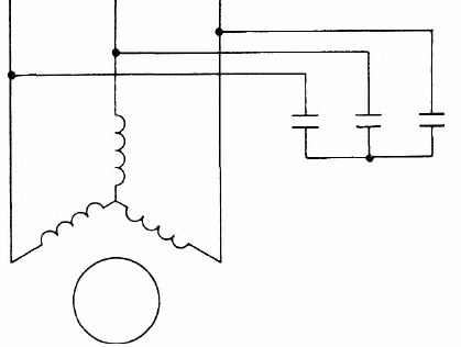
Rice. 3. Schematic of dynamic braking of a self-excited induction motor
As the rotor rotates, an EMF is created in the stator circuit due to residual magnetization and current flow through the stator windings as well as through the capacitors.When a certain speed is reached in the stator circuit, resonant conditions occur: the sum of the inductive resistances will equal the capacitive resistance. An intensive process of self-excitation of the machine will begin, which will lead to an increase in EMF. The self-excitation mode will end when the EMF of the machine E and the voltage drop across the capacitors are equal.
The maximum braking torque with increasing capacity shifts to lower speeds. The disadvantages of the considered braking mode are the appearance of braking action only within a certain speed zone and the need to use large capacitors for braking at low speeds.
On the plus side, no additional source of electrical power is required. This mode is always implemented in installations where a capacitor bank is connected to the motor to improve the power factor of the supply network.
See also on this topic: Brake circuits for asynchronous motors