Three-phase motor control, methods of motor speed control
The control of asynchronous motors can be either parametric, that is, by changing the parameters of the machine circuits, or by a separate converter.
Parametric control
The critical slip depends weakly on the active resistance of the stator circuit. When additional resistance is introduced into the stator circuit, the value decreases slightly. The maximum torque may be significantly reduced. As a result, the mechanical characteristic will take the form shown in Fig. 1.
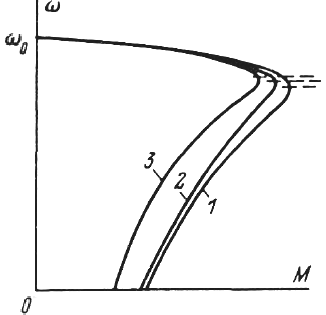
Rice. 1. Mechanical characteristics of an asynchronous motor when changing the parameters of the primary and secondary circuit: 1 — natural, 2 and 3 — with the introduction of additional active and inductive resistance in the stator circuit
Comparing it with the natural characteristic of the motor, we can conclude that the introduction of additional resistance in the stator circuit has little effect on the speed. At constant static torque, the speed will decrease slightly.Therefore, this rate control method is inefficient and is not used in this simplest version.
Introducing inductive resistance into the stator circuit is also ineffective. Critical slip will also decrease slightly, and engine torque is significantly reduced due to the increase in drag. The corresponding mechanical characteristic is shown in the same fig. 1.
Sometimes an additional resistance is introduced in the stator circuit to limit inrush currents… In this case, chokes are usually used as additional inductive resistance, and thyristors are used as active ones (Fig. 2).
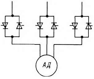
Rice. 2. Including thyristors in the stator circuit
However, it should be borne in mind that this significantly reduces not only the critical, but also motor starting torque (in c = 1), which means that starting under these conditions is possible only with a small static moment. The introduction of additional resistance in the rotor circuit is, of course, only possible for a wound-rotor motor.
The additional inductive resistance in the rotor circuit has the same effect on the speed of the motor as when it is introduced in the stator circuit.
In practice, the use of inductive resistance in a rotor circuit is extremely difficult due to the fact that it must operate at a variable frequency — from 50 Hz to several hertz and sometimes fractions of a hertz. Under such conditions, it is very difficult to create a choke.
At low frequency, the active resistance of the inductor will mainly affect. Based on the above considerations, inductive resistance in the rotor circuit is never used for speed control.
The most effective way of parametric speed control is to introduce additional active resistance in the rotor circuit. This gives us a family of characteristics with constant maximum torque. These characteristics are used to limit current and maintain a constant torque, and can also be used to control speed.
In fig. 3 shows how by changing r2, i.e. input rext, it is possible at some static moment to change the speed over a wide range — from nominal to zero. In practice, however, it is possible to adjust the speed only for sufficiently large values of the static moment.
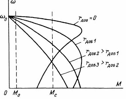
Rice. 3. Mechanical characteristics of an asynchronous motor with the introduction of additional resistance in the rotor circuit
At low values of (Mo) in the near-idle mode, the speed control range is greatly reduced and very large additional resistances will have to be introduced to reduce the speed appreciably.
It should be borne in mind that when operating at low speeds and with high static torques, the speed stability will be insufficient, because due to the high steepness of the characteristics, slight fluctuations in the torque will cause significant changes in speed.
Sometimes, in order to provide acceleration of the motor without successive removal of the rheostat sections, a rheostat and an inductive coil are connected in parallel to the rotor rings (Fig. 4).
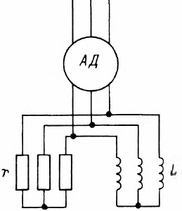
Rice. 4. Parallel connection of additional active and inductive resistance in the rotor circuit of the asynchronous motor
At the initial moment of starting, when the frequency of the current in the rotor is high, the current is mainly closed through the rheostat, i.e.through a large resistance that provides a sufficiently high starting torque. As the frequency decreases, the inductive resistance decreases and the current begins to close through the inductance as well.
When operating speeds are reached, when slip is small, the current flows mainly through the inductor, whose resistance at low frequency is determined by the electrical resistance of the winding rrev. Thus, at start-up, the external resistance of the secondary circuit is automatically changed from rreost to roro, and acceleration occurs at practically constant torque.
Parametric control is naturally associated with large energy losses. The slip energy, which in the form of electromagnetic energy is transmitted through the gap from the stator to the rotor and is usually converted into mechanical, with a large resistance of the secondary circuit, goes mainly to heat this resistance, and at s = 1 all the energy transferred from stator to rotor, will be consumed in the rheostats of the secondary circuit (Fig. 5).
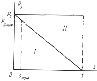
Rice. 5. Losses in the secondary circuit when adjusting the speed of an asynchronous motor by introducing additional resistance in the rotor circuit: I — zone of useful power transmitted to the motor shaft, II — zone of losses in the resistances of the secondary circuit
Therefore, parametric control is mainly used for short-term speed reduction in the course of the technological process carried out by the working machine.Only in cases where speed regulation processes are combined with starting and stopping of the working machine, as for example in lifting installations, parametric control with the introduction of additional resistance in the rotor circuit is used as the main means of speed control.
Speed regulation by varying the voltage applied to the stator
When adjusting the speed of an induction motor by changing the voltage, the shape of the mechanical characteristic remains unchanged, and the moments decrease in proportion to the square of the voltage. The mechanical characteristics at different stresses are shown in Fig. 6. As you can see, in the case of using conventional motors, the speed control range is very limited.
Rice. 6… Regulation of the speed of an induction motor by changing the voltage in the stator circuit
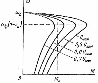
A slightly wider range can be achieved with a high slip motor. However, in this case, the mechanical characteristics are steep (Fig. 7) and stable operation of the engine can be achieved only with the use of a closed system that provides speed stabilization.
When the static torque changes, the control system maintains a given speed level and a transition from one mechanical characteristic to another occurs. As a result, operation continues at the characteristics shown by the dashed lines.
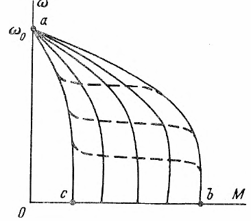
Rice. 7. Mechanical characteristics when adjusting the stator voltage in a closed system
When the drive is overloaded, the motor reaches the limit characteristic corresponding to the maximum possible voltage that the converter provides, and as the load increases further, the speed will decrease according to this characteristic. At low load, if the converter cannot reduce the voltage to zero, there will be a speed increase according to the AC characteristic.
Magnetic amplifiers or thyristor converters are usually used as a voltage-controlled source. In the case of using a thyristor converter (Fig. 8), the latter usually works in pulse mode. In this case, a certain average voltage is maintained at the stator terminals of the induction motor, which is necessary to ensure a given speed.
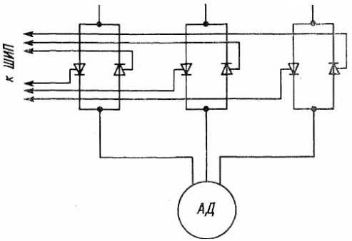
Rice. 8. Scheme of impulse speed control of an induction motor
To regulate the voltage at the motor stator terminals it would seem possible to use a transformer or autotransformer with sectional windings. However, the use of separate transformer blocks is associated with very high costs and does not provide the necessary quality of regulation, since in this case only a stepwise change of voltage is possible, and it is practically impossible to introduce a section switching device into an automatic system. Autotransformers are sometimes used to limit the inrush currents of powerful motors.
Speed control by switching stator winding sections to different number of pole pairs
There are a number of production mechanisms that during the technological process must work at different speed levels, while there is no need for smooth regulation, but it is enough to have a drive with a discrete, stepwise, speed change. Such mechanisms include some metalworking and woodworking machines, elevators, etc.
A limited number of fixed rotational speeds can be achieved multi-speed squirrel-cage motors, in which the stator winding switches to a different number of pole pairs. The squirrel cell of a squirrel cell motor automatically forms the number of poles equal to the number of stator poles.
Two motor designs are used: with multiple windings in each stator slot, and with a single winding whose sections are switched to produce a different number of pole pairs.
Multi-speed motors with several independent stator windings are inferior to single-winding multi-speed motors in technical and economic terms. In multi-winding motors, the stator winding is used inefficiently, the filling of the stator slot is insufficient, the efficiency and cosφ are below optimum. Therefore, the main distribution is obtained from multi-speed single-winding motors with switching of the windings on different number of pole pairs.
When switching sections, the MDS distribution in the stator bore changes. As a result, the rotation speed of the MDS also changes, and hence the magnetic flux. The easiest way is to switch pairs of poles with a ratio of 1: 2. In this case, the windings of each phase are made in the form of two sections.Changing the direction of the current in one of the sections allows you to halve the number of pole pairs.
Consider the circuits of the stator winding of the motor, the sections of which are switched to eight and four poles. In fig. 9 shows a single-phase winding for simplicity. When two sections are connected in series, that is, when the end of the first section K1 is connected to the beginning of the second H2, we get eight poles (Fig. 9, a).
If we change the direction of the current in the second section to the opposite, then the number of poles formed by the coil will be reduced by half and will be equal to four (Fig. 9, b). The direction of the current in the second section can be changed by transferring the jumper from the terminals K1, H2 to the terminals K1, K2. Also, four poles can be obtained by connecting sections in parallel (Fig. 9, c).
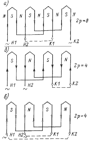
Rice. 9. Switching sections of the stator winding to a different number of pole pairs
The mechanical characteristics of a two-speed motor with switched stator windings are shown in Fig. ten.
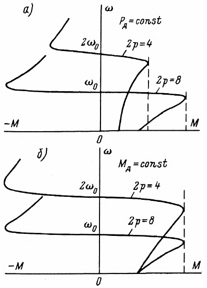
Rice. 10. Mechanical characteristics of an induction motor when switching the stator winding of different number of pole pairs
When switching from scheme a to scheme b (Fig. 9), constant engine power is maintained at both speed levels (Fig. 10, a). When using the second shift option, the engine can develop the same torque. It is possible to switch sections of the stator winding, providing a speed ratio not only 1: 2, but also others. In addition to two-speed engines, the industry also produces three- and four-speed engines.
Frequency control of three-phase motors
As follows from the above, the speed regulation of the induction motor is extremely difficult. Infinitely variable speed control over a wide range while maintaining sufficient stiffness of characteristics is only possible with partial control. By changing the frequency of the supply current and therefore the speed of rotation of the magnetic field, it is possible to adjust the speed of rotation of the motor rotor.
However, to control the frequency in the installation, a frequency converter is needed, which could convert a constant frequency current of the supply network of 50 Hz into a variable frequency current smoothly varying over a wide range.
Initially, there were attempts to use converters on electric machines. However, to obtain variable frequency current from a synchronous generator, it is necessary to rotate its rotor at variable speed. In this case, the tasks of regulating the speed of the running engine are assigned to the engine that drives the synchronous generator in rotation.
The collector generator, which can generate a current of variable frequency at a constant speed of rotation, also did not allow solving the problem, because, firstly, a current of variable frequency is needed to excite it, and secondly, like all AC collector machines, great difficulties arise, ensuring normal commutation of the collector.
In practice, frequency control began to develop with the advent of semiconductor devices… At the same time, it turned out to be possible to create frequency converters for controlling both power plants and executive motors in servo systems and servo drives.
Along with the complexity of designing a frequency converter, there is also the need to simultaneously control two quantities — frequency and voltage. When the frequency decreases to decrease the speed, the EMF and grid voltage balance can only be maintained by increasing the motor's magnetic flux. In this case, the magnetic circuit will saturate and the stator current will increase intensively according to a non-linear law. As a result, the operation of an induction motor in frequency control mode at constant voltage is impossible.
By reducing the frequency, in order to keep the magnetic flux unchanged, it is necessary to simultaneously reduce the voltage level. Thus, in frequency control, two control channels must be used: frequency and voltage.
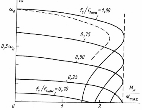
Rice. 11. Mechanical characteristics of an induction motor when supplied with voltage of controlled frequency and constant magnetic flux
Frequency control systems are usually built as closed loop systems and more information about them is given here: Frequency regulation of an asynchronous motor