What is a voltage inverter, how it works, the use of an inverter
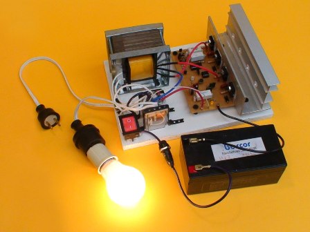
Special electronic power supplies called inverters are used to convert direct current into alternating current. Most often, an inverter converts a DC voltage of one magnitude into an AC voltage of another magnitude.
Therefore, the inverter is a generator of periodically changing voltage, while the voltage waveform can be sinusoidal, near-sinusoidal or pulsed... Inverters are used both as independent devices and as part of uninterruptible power supply systems (UPS).
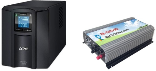
As part of uninterruptible power sources (UPS), inverters allow, for example, to receive continuous power to computer systems, and if the voltage suddenly disappears in the network, the inverter will immediately start supplying the computer with energy obtained from the backup battery. At least the user will have time to turn off and turn off the computer.
Larger uninterruptible power supplies use more powerful inverters with large capacity batteries that can autonomously power consumers for hours regardless of the grid, and when the grid returns to normal, the UPS will automatically switch consumers directly to the mains and batteries will start charging.
The technical side
In modern electricity conversion technologies, the inverter can only act as an intermediate unit, where its function is to convert the voltage through a high-frequency transformation (tens and hundreds of kilohertz). Fortunately, today this problem can be easily solved, because for the development and design of inverters, both semiconductor switches capable of withstanding currents of hundreds of amperes, magnetic cores with the necessary parameters and electronic microcontrollers specially designed for inverters (including resonant) available.
The requirements for inverters, as well as for other power devices, include: high efficiency, reliability, the smallest possible dimensions and weight. It is also necessary for the inverter to withstand the permissible level of higher harmonics in the input voltage and not create unacceptably loud impulse noise for users.
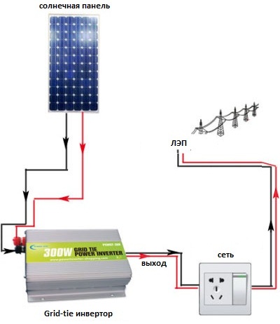
In systems with "green" sources of electricity (solar panels, wind mills) to supply electricity directly to the general grid, Grid-tie inverters are used, which can work synchronously with the industrial grid.
During the operation of the voltage inverter, the constant voltage source is periodically connected to the load circuit with variable polarity, while the frequency of the connections and their duration are formed by a control signal that comes from the controller.
The controller in the inverter usually performs several functions: regulating the output voltage, synchronizing the operation of semiconductor switches, protecting the circuit from overload. In general, inverters are divided into: stand-alone inverters (current and voltage inverters) and dependent inverters (grid-driven, grid-driven, etc.)
Inverter circuit
The inverter's semiconductor switches are controlled by the controller and have reverse shunt diodes. The output voltage of the inverter, depending on the current power of the load, is adjusted by automatically changing the pulse width in the high-frequency converter, in the simplest case PWM (Pulse Width Modulation).
The half-waves of the output low-frequency voltage must be symmetrical so that the load circuits do not in any case receive a significant constant component (for transformers this is especially dangerous), for this the pulse width of the LF block (in the simplest case) is made constant .
In the control of the output switches of the inverter, an algorithm is used that ensures a sequential change in the structures of the power circuit: direct, short-circuit, reverse.
One way or another, the instantaneous load power value at the output of the inverter has the character of double-frequency waves, therefore the primary source must allow such a mode of operation when ripple currents flow through it, and withstand a corresponding level of interference (at the inverter input).
If the first inverters were exclusively mechanical, today there are many options for semiconductor inverter circuits and there are only three typical schemes: a bridge without a transformer, a push with the zero terminal of the transformer, a bridge with a transformer.
The transformerless bridge circuit is found in 500 VA uninterruptible power supplies and automotive inverters. The sliding circuit with the neutral terminal of the transformer is used in low-power UPS (for computers) with a capacity of up to 500 VA, where the backup battery voltage is 12 or 24 volts. The bridge circuit with a transformer is used in powerful sources of uninterruptible power supply (for units and tens of kVA).
Output voltage waveform
In rectangular voltage inverters, a group of reverse diode switches is switched at the output so as to produce an alternating voltage across the load and provide a controlled circulation mode in the circuit reactive energy.
The following are responsible for the proportionality of the output voltage: the relative duration of the control pulses or the phase shift between the control signals of the key groups. In uncontrolled reactive power circulation mode, the user influences the shape and magnitude of the inverter output voltage.
In voltage inverters with a step-shaped output, the high-frequency pre-converter forms a unipolar step-voltage curve, approximately approximating in shape to a sine wave whose period is half the period of the output voltage. The LF bridge circuit then converts the unipolar step curve into two halves of a bipolar curve that roughly resembles a sine wave.
In voltage inverters with a sinusoidal (or near-sinusoidal) shape of the output, the high-frequency pre-converter generates a constant voltage close in amplitude to the future sinusoidal output.
The bridge circuit then forms a low-frequency variable from a constant voltage, by means of multiple PWMs, when each pair of transistors in each half-cycle of forming the output sine wave is opened several times for a time varying according to the harmonic law. A low-pass filter then extracts a sine from the resulting waveform.
HF pre-conversion circuits in inverters
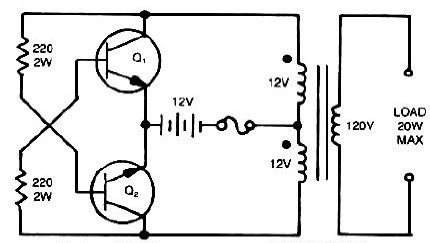
The simplest high-frequency preconversion circuits in inverters are self-generating. They are quite simple in terms of technical implementation and are quite efficient at low powers (up to 10-20 W) to supply loads that are not critical to the power supply process. The frequency of the oscillators is no more than 10 kHz.
Positive feedback in such devices is obtained by saturating the transformer magnetic circuit. But for powerful inverters, such schemes are not acceptable, since the losses in the switches increase, and the efficiency is ultimately low.Also, any short circuit at the output interrupts the self-oscillations.
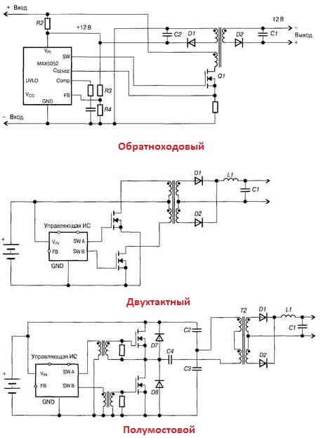
The better circuits of the preliminary high-frequency converters are flyback (up to 150 W), push-pull (up to 500 W), half-bridge and bridge (more than 500 W) of PWM controllers, where the conversion frequency reaches hundreds of kilohertz.
Types of inverters, modes of operation
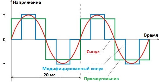
Single-phase voltage inverters are divided into two groups: with a pure sine wave at the output and with a modified sine wave. Most modern devices allow a simplified form of the network signal (modified sine wave).
A pure sine wave is important for devices that have an electric motor or transformer at the input, or if it is a special device that only works with a pure sine wave at the input.
Three-phase inverters are generally used to generate three-phase current for electric motors, for example for power supply three-phase asynchronous motor… In this case, the motor windings are directly connected to the inverter output. In terms of power, the inverter is selected based on its peak value for the user.
In general, there are three modes of operation of the inverter: start, continuous and overload. In the start-up mode (charging the capacity, starting the refrigerator) the power can double the rating of the inverter in a fraction of a second, this is acceptable for most models. Continuous mode - corresponding to the rated value of the inverter. Overload mode — when the user's power is 1.3 times the rated one — in this mode, the average inverter can work for about half an hour.