Electrical and temporal parameters of rectangular pulses
They are usually called periodic and non-periodic signals, the shape of which differs from sinusoidal pulse signals... The processes of generation, conversion, as well as questions about the practical application of pulse signals are related today to many areas of electronics.
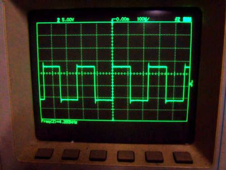
So, for example, no modern power supply is complete without a square wave generator located on its printed circuit board, such as, for example, on the TL494 microcircuit, which produces pulse trains with parameters suitable for the current load.
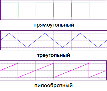
Since pulse signals can have a different shape, they call different pulses according to a similar geometric shape: rectangular pulses, trapezoidal pulses, triangular pulses, sawtooth pulses, step pulses and pulses of various other shapes. Meanwhile, it is precisely rectangular pulses... Their parameters will be considered in this article.
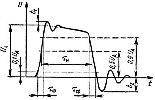
Of course, the term «rectangular impulse» is somewhat arbitrary. Due to the fact that there is nothing perfect in nature, just as there are no perfectly rectangular pulses.In fact, a real pulse, which is usually called rectangular, can also have oscillating waves (shown as b1 and b2 in the figure), due to very real capacitive and inductive factors.
These emissions, of course, may be absent, but there are electrical and temporal parameters of the pulses, reflecting, among other things, "the imperfection of their squareness".
A rectangular pulse has a specific polarity and operating level. Most often, the polarity of the pulse is positive, since the majority of digital microcircuits are powered by a positive voltage relative to the common wire, and therefore the instantaneous value of the voltage in the pulse is always greater than zero.
But there are, for example, comparators powered by bipolar voltage; in such schemes you can find bipolar pulses. In general, negative-polarity integrated circuits are not as widely used as conventional positive-supply integrated circuits.
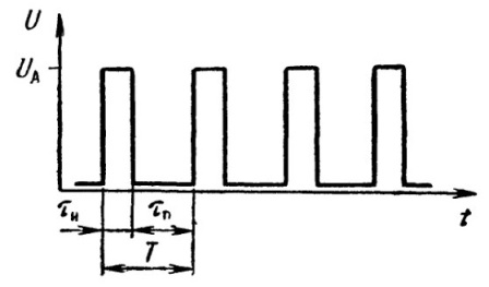
In a pulse sequence, the operating voltage of the pulse can be low or high, with one level replacing another over time. The low voltage level is denoted by U0, the high level by U1. The highest instantaneous value of the voltage in a pulse Ua or Um, relative to the initial level of the pulse amplitude, is called.
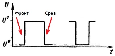
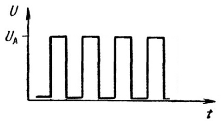
Pulse device designers often work with high-level active pulses, such as the one shown at left. But sometimes it is practically advisable to use low-level pulses as active, for which the initial state is a high voltage level. A low-level pulse is shown in the figure to the right. Calling a low-level impulse a "negative impulse" is illiterate.
The voltage drop in a rectangular pulse is called a front, which represents a rapid (commensurate in time with the time of the transient process in the circuit) change in the electrical state.
The low-to-high slope, that is, a positive slope, is called the leading edge or simply the edge of the pulse. The high-to-low or negative edge is called the clipping, slope, or simply the trailing edge of the pulse.
The front end is denoted in the text 0.1 or schematically _ |, and the last 1.0 or schematically | _.
Depending on the inertial characteristics of the active elements, the transient process (dropout) in a real device always takes some finite time. Therefore, the total pulse duration includes not only the existence times of the high and low levels, but also the duration times of the edges (leading and trailing), which are denoted by Tf and Tav. In almost any particular chart, the rise and fall time can be seen with oscilloscope.
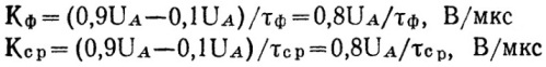
Since in reality the moments of the beginning and end of the transients in the drops are not easy to distinguish very precisely, it is customary to consider the duration of the drop as the time interval during which the voltage changes from 0.1 Ua to 0.9 Ua ( front) or from 0.9Ua to 0.1Ua (cut). So are the front steepness Kf and the cut steepness Ks. are set according to these limit states and are measured in volts per microsecond (V / μs). The duration of the pulse is called the time interval counted from the level of 0.5Ua.
When the processes of formation and generation of pulses are considered as a whole, the front and clipping are assumed to be zero in duration, since these small time intervals are not critical for coarse calculations.
Pulse sequence — these are pulses following one another in a certain order. If the pauses between the pulses and the duration of the pulses in the sequence are equal to each other, it is a periodic sequence. The pulse repetition period T is the sum of the pulse duration and the pause between pulses in the sequence. The pulse repetition rate f is the reciprocal of the period.
Periodic sequences of rectangular pulses, in addition to period T and frequency f, are characterized by several additional parameters: duty cycle DC and duty cycle Q. Duty cycle is the ratio of the duration of the pulse to its period.
Wellness The ratio of the period of the pulse to the time of its duration. A periodic sequence of duty cycle Q = 2, that is, one in which the pulse width is equal to the pause time between pulses or in which the duty cycle is DC = 0.5, is called a square wave.