Rectifier control
The word «valve» in the engine name comes from the word «valve», which means a semiconductor switch. Thus, in principle, the drive can be called a valve drive if its mode of operation is controlled by a special converter of controlled semiconductor switches.
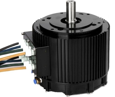
The valve drive itself is an electromechanical system consisting of a synchronous machine with permanent magnets on the rotor and an electronic commutator (which powers the stator windings) with an automatic sensor-based control system.
In those many areas of technology where asynchronous motors or DC machines have traditionally been installed, today precisely valve motors can often be found as magnetic materials become cheaper and the basis of semiconductor electronics and control systems develops very fast .
Permanent magnet rotor synchronous motors have a number of advantages:
-
there is no device for collecting brushes, therefore the motor resource is longer and its reliability is higher than that of machines with sliding contacts, in addition, the range of operating revolutions is higher;
-
a wide range of supply voltages of the windings; significant torque overload is allowed — more than 5 times;
-
high dynamics of the moment;
-
it is possible to adjust the speed with the preservation of the torque at low revolutions or with the preservation of the power at high revolutions;
-
Efficiency over 90%;
-
minimal idle losses;
-
small features of weight and size.
Neodymium-iron-boron magnets are fully capable of creating an induction in the gap of the order of 0.8 T, that is, at the level of asynchronous machines, and the main electromagnetic losses in such a rotor are absent. This means that the line load on the rotor can be increased without increasing the total losses.
This is the reason for the higher electromechanical efficiency. valve engines compared to other brushless machines such as induction motors. For the same reason, valve motors now occupy a worthy place in the catalogs of leading foreign and domestic manufacturers.
Control of the inverter switches on a permanent magnet motor is traditionally done as a function of its rotor position. The high performance characteristics thus achieved make valve actuation very promising in the small and medium power range for automation systems, machine tools, robots, manipulators, coordinate devices, processing and assembly lines, guidance and tracking systems, for aviation, medicine, transport, etc. .g.
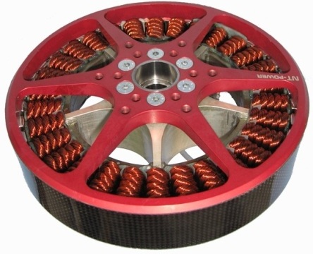
In particular, traction disc valve motors with a power of more than 100 kW are produced for urban electric transport. Here, neodymium-iron-boron magnets are used with alloying additives that increase the coercive force and increase the operating temperature of the magnets to 170 ° C, so that the motor can easily withstand short-term five-fold current and torque overloads.
Steering drives for submarines, land and aircraft, wheel motors, washing machines—valve motors find useful applications in many places today.
Valve motors are of two types: direct current (BLDC — brushless DC) and alternating current (PMAC — permanent magnet AC). In DC motors, the trapezoidal EMF of rotation in the windings is due to the arrangement of the rotor magnets and the stator windings. In AC motors, the electromotive force of rotation is sinusoidal. In this article we will talk about the control of a very common type of brushless motor - BLDC (direct current).
DC valve motor and its control principle BLDC motors are distinguished by the presence of a semiconductor switch that acts instead of the brush-collecting block that is characteristic of DC machines with stator winding and magnetic rotor.
Switching of the valve motor commutator takes place depending on the current position of the rotor (depending on the position of the rotor). Most often, the stator winding is three-phase, the same as that of a star-connected induction motor, and the construction of the permanent magnet rotor can be different.
The driving moment in BLDC is formed as a result of the interaction of the magnetic fluxes of the stator and the rotor: the magnetic flux of the stator all the time tends to rotate the rotor in such a position that the magnetic flux of the permanent magnets installed on it coincides in direction with the magnetic flux of the stator.
In the same way, the Earth's magnetic field orients the compass needle—it unfolds it "along the field." The rotor position sensor allows you to keep the angle between the flows constant at the level of 90 ± 30 °, in this position the torque is maximum.
The BLDC stator winding power supply semiconductor switch is a controlled semiconductor converter with a hard 120 ° algorithm for switching voltages or currents of three operating phases.
An example of a functional diagram of the power section of a converter with the possibility of regenerative braking is shown in the figure above. Here, the inverter with amplitude-pulse modulation of the output is included IGBT transistors, and the amplitude is adjusted thanks to pulse width modulation on an intermediate DC link.
Basically, for this purpose, thyristor frequency converters with an autonomous voltage or current inverter with power control and transistor frequency converters with an autonomous voltage inverter controlled in PWM mode or with relay regulation of the output current are used.
As a result, the electromechanical characteristics of the motor are similar to traditional DC machines with magnetoelectric or independent excitation, which is why BLDC control systems are built according to the classical principle of slave coordinate control of a DC drive with rotor revolutions and current loops of the stator.
For the correct operation of the commutator, a capacitive or inductive discrete sensor coupled with the pole motor can be used as a sensor or system based on Hall effect sensors with permanent magnets.
However, the presence of a sensor often complicates the design of the machine as a whole, and in some applications the rotor position sensor cannot be installed at all. Therefore, in practice, they often resort to the use of "sensorless" control systems. The sensorless control algorithm is based on the analysis of data directly from the inverter terminals and the current frequency of the rotor or power supply.
The most popular sensorless algorithm is based on calculating the EMF for one of the phases of the motor, disconnected from the power supply at the moment. The EMF transition of the off phase through zero is fixed, a shift of 90 ° is determined, the moment in time at which the middle of the next current pulse should fall is calculated. The advantage of this method is its simplicity, but there are also disadvantages: at low speeds, it is quite difficult to determine the moment of zero crossing; the deceleration will only be accurate at a constant rotational speed.
Meanwhile, for more accurate control, complex methods are used to estimate the position of the rotor: according to the connection of the flux of the phases, according to the third harmonic of the EMF of the windings, according to changes in the inductance of the phase windings.
Consider an example of monitoring streaming connections. BLDC torque ripple when the motor is supplied with rectangular voltage pulses is known to reach 25%, resulting in uneven rotation, creating a speed control limit below. Therefore, currents close to square shape are formed in the stator phases by means of closed control loops.