Scalar and vector control of induction motors - what's the difference?
Asynchronous engine — an AC motor in which currents in the stator windings create a rotating magnetic field. This magnetic field induces currents in the rotor winding and, acting on these currents, carries the rotor with it.
However, in order for the rotating stator magnetic field to induce currents in a rotating rotor, the rotor in its rotation must lag slightly behind the rotating stator field. Therefore, in an induction motor, the speed of the rotor is always slightly less than the speed of rotation of the magnetic field (which is determined by the frequency of the alternating current feeding the motor).
The deceleration of the rotor by the rotating magnetic field of the stator (rotor slippage) the more, the greater the motor load. The lack of synchronization between the rotation of the rotor and the magnetic field of the stator is a characteristic feature of the induction motor, hence its name.
The rotating magnetic field in the stator is generated by windings supplied with phase-shifted currents. Three-phase alternating current is usually used for this purpose. There are also single-phase induction motors where the phase shift between the currents in the windings is created by including different reactances in the windings.
To regulate the angular speed of rotation of the rotor, as well as the torque on the shaft of modern brushless motors, vector or scalar control of the electric drive is used.
Scalar control
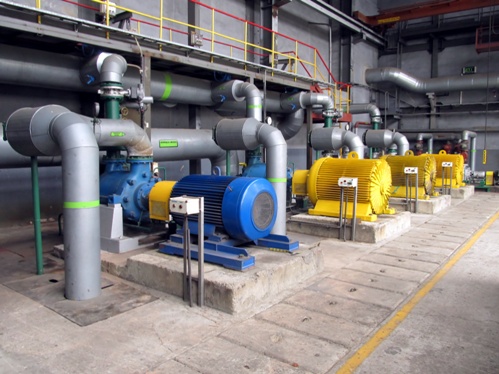
It was the most common control of a scalar induction motor, when, for example, to control the rotation speed of a fan or pump it is sufficient to maintain a constant rotation speed of the rotor, for this a feedback signal from a pressure sensor or from a speed sensor is sufficient.
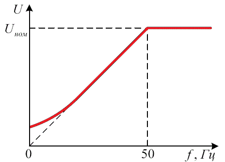
The principle of scalar control is simple: the amplitude of the supply voltage is a function of frequency, the voltage to frequency ratio being approximately constant.
The specific form of this dependence is related to the load on the shaft, but the principle remains the same: we increase the frequency, and the voltage proportionally increases depending on the load characteristic of the given motor.
As a result, the magnetic flux in the gap between the rotor and the stator is kept almost constant. If the voltage-to-frequency ratio deviates from the rated for a motor, then the motor will be either over-excited or under-excited, resulting in motor losses and process malfunctions.
Thus, scalar control makes it possible to achieve almost constant shaft torque in the operating frequency range, regardless of frequency, but at low revolutions the torque still decreases (to prevent this, it is necessary to increase the voltage -ratio to frequency ), therefore, for each engine there is a strictly defined operating scalar control range.
Also, it is impossible to build a scalar speed control system without a shaft-mounted speed sensor because the load greatly affects the lag of the actual rotor speed from the supply voltage frequency. But even with a speed sensor with scalar control, it will not be possible to adjust the torque with high accuracy (at least not economically feasible).
This is the disadvantage of scalar control, which explains the relative scarcity of its applications, limited mainly to conventional induction motors, where the dependence of slip on the load is not critical.
Vector control
To get rid of these shortcomings, in 1971, Siemens engineers proposed to use vector control of the motor, in which the control is carried out with feedback on the magnitude of the magnetic flux. The first vector control systems contained flow sensors in the motors.
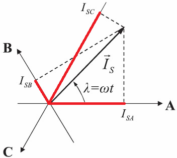
Today, the approach to this method is slightly different: the mathematical model of the motor allows you to calculate the rotor speed and the shaft moment depending on the current phase currents (from the frequency and values of the currents in the stator windings).
This more progressive approach enables independent and almost inertial control of both shaft torque and shaft speed under load, as the control process also takes into account the phases of the currents.
Some more precise vector control systems are equipped with speed feedback loops, while control systems without speed sensors are called sensorless.
So, depending on the field of application of this or that electric drive, its vector control system will have its own characteristics, its own degree of regulation accuracy.
When the accuracy requirements for speed regulation allow a deviation of up to 1.5% and the regulation range does not exceed 1 in 100, then the sensorless system is fine. If the accuracy of speed adjustment with a deviation of no more than 0.2% is required, and the range is reduced to 1 to 10,000, then it is necessary to have feedback for the shaft speed sensor. The presence of a speed sensor in vector control systems allows precise torque control even at low frequencies down to 1 Hz.
So, vector control has the following advantages. High accuracy of rotor speed regulation (and without a speed sensor on it) even under conditions of dynamically changing shaft load, while there will be no kicks. Smooth and even rotation of the shaft at low revolutions. High efficiency due to low losses under conditions of optimal supply voltage characteristics.
Vector control is not without its drawbacks. The complexity of computational operations.The need to set the initial data (variable drive parameters).
For a group electric drive, vector control is fundamentally unsuitable, here scalar control is better.