Disadvantages of thyristor converters
The main type of DC motor converters currently is the solid state thyristor.
Disadvantages of thyristors include the following:
1. One-sided conduction, as a result of which it is necessary to double the number of devices.
2. Small overload current as well as limiting the rate of rise of the current.
3. Sensitivity to overvoltage.
The average value of the rectified voltage in the absence of regulation is mainly determined by the switching circuit of the thyristor converter. Conversion circuits are divided into two classes: zero terminal and bridge. In medium and high power installations, bridge converter circuits are mainly used, which is mainly due to two reasons:
-
lower voltage of each of the thyristors,
-
the absence of a constant component of the current flowing through the windings of the transformer.
Converter circuits can also differ in the number of phases: from one in low-power installations to 12-24 in high-power converters.
All variants of thyristor converters, along with positive properties, such as low inertia, lack of rotating elements, smaller (compared to electromechanical converters) sizes, have a number of disadvantages:
1. Hard connection to the mains: all fluctuations in the mains voltage are transmitted directly to the drive system, and load surges on the motor axles are immediately transmitted to the mains and cause current surges.
2. Low power factor when adjusting the voltage down.
3. Generation of higher harmonics, load on the power grid.
In connection with the unipolar conductivity of thyristors and the converter in general, the reverse of the motor in the simplest circuit in the presence of one converter can be done only by switching the armature or the excitation coil using suitable contactors. Naturally, under this condition, the operation of the electric machine system will be unsatisfactory, since it is necessary to switch either high currents or a high inductance circuit. Therefore, two converters are usually used, each of which is designed to work in one direction of rotation.
The technical and economic indicators of a thyristor drive: the range of speed regulation, the possibility of one or another method of braking, reversing, the type of mechanical characteristics and others are largely predetermined by the power supply scheme.
The whole variety of schemes of the main (power) circuits can be reduced to four main options:
1. DC motor armature supply from one controlled converter.This and the following diagrams to simplify the drawing and identify fundamental differences are given under the assumption of supply from a single-phase AC network.
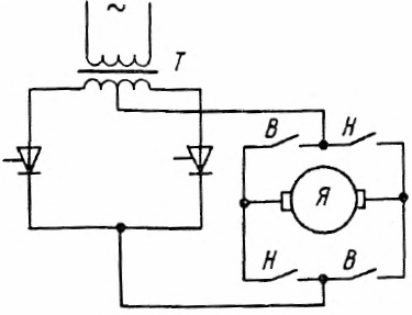
Controlled converter-motor system with one thyristor converter in the armature circuit, V, N - contactors for forward and reverse rotation
In this case, speed regulation is provided only by changing the voltage applied to the motor armature; motor reverse — by changing the direction of the armature current using contactors. Braking is electrodynamic.
The presence of reversing contactors in the armature circuit makes the installation more expensive, especially with significant motor power, and also makes it suitable only for mechanisms that do not require frequent reversals and stops. The circuit does not provide regenerative braking capability.
2. Supplying the motor armature from two converters connected in a cross circuit. In one direction of rotation, one inverter works, in the other - the other. The opposite is achieved by controlling the thyristors and is ensured by transferring one of the converters to inverter mode.
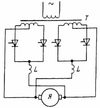 A controlled inverter-motor system with two inverters connected in a cross circuit
The circuit does not require bulky reversing contactors in the armature circuit, provides a smooth and reliable energy recovery stop and is generally used for frequent reversing.
The disadvantage of the circuit is the complexity and high cost due to the need to have a double set of thyristors and double the number of secondary windings of the power transformer.
3. Parallel-opposite connection of converters. The properties of the scheme are similar to the previous one.The advantage is fewer secondary windings of the power transformer.
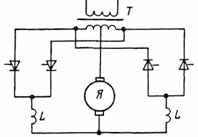
Controlled inverter-motor system with parallel opposite connection of converters
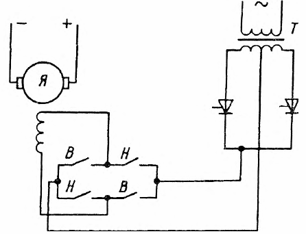
A converter-motor system with a controlled converter in the motor excitation circuit
The device operates with a constant and sufficiently high power factor. Conversely, by changing the direction of the current in the excitation circuit, it tightens the transients. The system is not very suitable for mechanisms that require a large number of reverses and stops.