What are current transformers for and how do they differ from voltage transformers
Speaking for the voltage transformer, we mean an electromagnetic device designed to convert alternating voltage with a certain frequency: from high to low or from low to higher, depending on the purpose of the transformer, and ultimately — from the transformation factor of this specimen. Using a voltage transformer electrical energy with a sufficiently high efficiency, it is transferred from the primary circuit to the secondary circuit, to which the load, that is, the consumer, is usually connected.
Nevertheless, the voltage of the secondary winding of a voltage transformer operating under normal or no-load load always remains almost unchanged, at least with high accuracy close to the rated voltage of the secondary winding of the transformer, i.e. it will lie within a certain known rather narrow range. But at the same time, the load current can be very different — it can vary from zero to the maximum allowable, depending on the impedance and the nature of the load that the transformer is currently supplying.
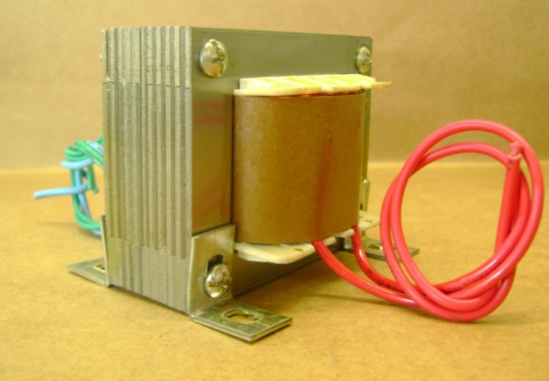
Current transformer differs significantly from the voltage transformer, both structurally and in terms of purpose and application. While the primary and secondary (or secondary, if there are several) windings of a voltage transformer often have a significant number of turns corresponding to the transformation ratio and core parameters, then the primary winding of the current transformer is only one turn passing through the window of the magnetic circuit. The secondary winding of a current transformer has many turns and is always connected to an active load of a strictly defined value, for example, a resistor.
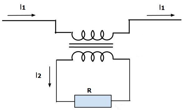
Now if across the primary winding alternating current will flow certain value, then the secondary winding loaded with a constant active load in the form of a resistor will create a voltage drop across it proportional to the current of the primary winding (via transformation factor) and load resistance. That is, depending on the current of the primary loop, the voltage of the secondary winding of the current transformer can vary in a wide range — from zero to the maximum permissible.
Obviously, this mode is different from the operating mode of the voltage transformer. Here (in the case of a current transformer), as a rule, there is no narrow range of nominal secondary voltages, typical of voltage transformers. Typical current transformer application — current measurement in circuits to which the load is already connected.
Current transformers, in addition to expanding the measurement limits, isolate the measuring devices from high voltage and make it possible to measure the current in networks with a voltage of more than 1000 V.
The primary winding of the current transformer has isolationrated for the full operating voltage of the network. To ensure the safety of service personnel (in case of insulation failure), one of the terminals of the secondary winding and the transformer core must be earthed.
In contrast from power transformers the secondary current in the current transformer depends on the primary current (measured current). Therefore, when working with a current transformer, it is necessary to pay special attention to the fact that so that the secondary winding is closed… For this purpose they have a device for closing the secondary winding when the measuring device is switched off.
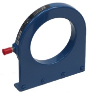
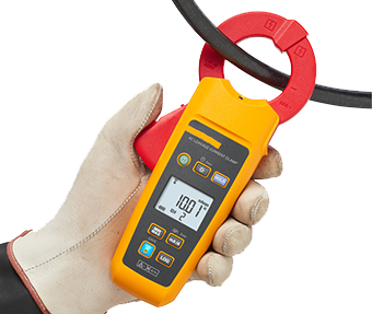
In cases where the live wire cannot be disconnected, transformers are used to connect the current transformer in the form current clamp… The core of such transformers consists of two halves connected by a hinge, which makes it possible to cover the current-carrying wire without breaking it. The secondary winding is short-circuited with an ammeter, which is usually attached to the core itself.
So, A voltage transformer is designed to convert electrical power to alternating current to supply loads of different ratings designed for the voltage on the secondary winding of the transformer.
Voltage transformers include power industrial transformers, substation transformers, network transformers, welding transformers, transformers in the power supplies of some household appliances, etc. These transformers can be either step-up or step-down.
Measuring voltage transformers are designed to convert high mains voltage into a voltage that can be measured by conventional instruments, i.e. to extend the measurement limits of AC instruments.
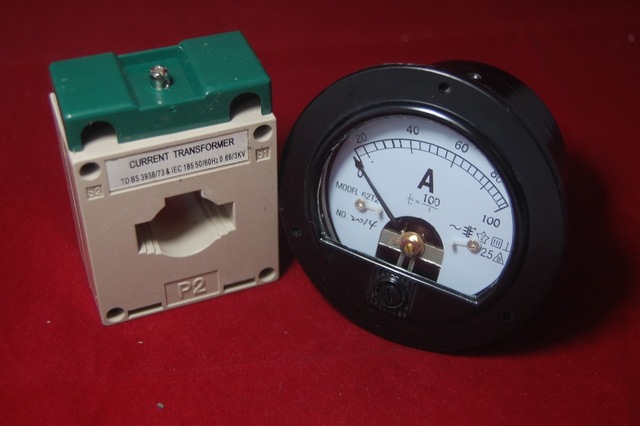
Current transformers are used for measurement — when it is necessary to ascertain the magnitude of the alternating current flowing through the wire. A current transformer is included in the break of this wire, and to its secondary winding is connected an ammeter or voltmeter connected to a resistor of known value.By simple calculations, it is easy to find the value of the current of the primary winding. Calculations can be performed by both humans and electronics.