Power filters
Various electronic devices require voltage sources to power the DC devices. Output voltage rectifiers has a pulsating appearance. In it you can select the average or DC component of the voltage and the variable component which is called ripple voltage or ripple of the output voltage.
Thus, the ripple determines the deviation of the instantaneous value of the output voltage from the average and can be both positive and negative. Voltage is characterized by two factors: frequency and amplitude of the waves. In rectifiers, the ripple frequency is either the same as the frequency of the input voltage (in a half-wave rectifier) or twice as high (in a full-wave rectifier).
In a half-wave rectifier, only one half-wave of the input voltage is used to obtain the output voltage, and the output voltage is in the form of unidirectional half-waves, following the frequency of the input voltage.
In full-wave rectifiers (both zero-point and bridge), the half-waves of the output voltage are formed by each half-wave of the input voltage. Therefore, the wave frequency here is twice as high as that network frequency… If the frequency of the current in the network is 50 Hz, then the frequency of the waves in the half-wave rectifier will be the same, and in the full-wave rectifier it is 100 Hz.
The amplitude of the rectifier output voltage ripple must be known in order. to determine the efficiency of the filters installed at the output of the rectifiers emitting the medium voltage component. This amplitude is usually characterized by the ripple factor (Erms), which is defined as the ratio of the effective value of the variable component of the output voltage to its average value (Edc):
r = Erms /Edc
The lower the ripple factor, the higher the efficiency of the filter. The ripple factor expressed as a percentage is also often used in practice:
(Erms /Edc)x100%.
Low pass filters are commonly used in power supplies. These filters pass from the input to the output, with almost no attenuation or attenuation, signals whose frequencies are below the cutoff frequency of the filter, and all higher frequencies are practically not transmitted to the output of the filter.
Filters are executable resistors, inductors and capacitors… The use of filters in the power supplies aims to smooth out the rectifier output voltage ripple and isolate the DC component of the voltage.
Filters used in power supply devices are divided into two main types:
-
filters with capacitive input,
-
inductive input filters.
Different combinations of the inclusion of filter elements are used, which have different names (U-shaped filter, L-shaped filter, etc.). The main filter type is determined by the filter element installed directly at the output of the rectifier.
In fig. 1a and 1b show the main types of filters. In the first of these, the filter capacitor is connected to the output of the rectifier and shunts the load. Through the filter capacitor, the main part of the AC component of the rectifier is closed. In the second, a filter choke is connected to the output of the rectifier, which forms a series circuit with the load and prevents any changes in the current in this series circuit.
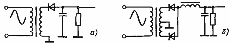
Rice. 1
A capacitive input filter provides a higher output voltage level than an inductive input filter, and an inductive input filter better reduces voltage ripple. Thus, it is advisable to use a capacitive input filter when a higher supply voltage is required, and an inductive input filter when a better DC output quality is required.
Capacitive input filter
Before considering the operation of complex filters, it is necessary to understand the operation of the simplest capacitive filter shown in Fig. 2a. Output voltage of the rectifier without filter on the displayyo in fig. 2b, and in the presence of a filter - in fig. 2c. In the absence of a filter capacitor, the voltage in Rl has a pulsating character. The average value of this voltage is the output voltage of the rectifier.
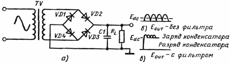
Rice. 2
In the presence of a filter capacitor, the main part of the alternating current component of the current is closed through the capacitor, bypassing the load Rl... With the appearance of the first half-wave of the output voltage the filter capacitor will begin to charge positive to the case, the voltage on it will change in accordance with the output voltage of the rectifier and at the end of half of the half-cycle will reach its maximum value.
In addition, the transformer secondary voltage drops and the capacitor begins to discharge through R1, keeping the positive voltage and current in the load at a higher level than it would be without the filter.
Before the capacitor can fully discharge, a second positive voltage half-wave occurs, again charging the capacitor to its maximum value. As soon as the secondary winding voltage starts to decrease, the capacitor will again start discharging to the load. In the future, the charge and discharge cycles of the capacitor alternate in each half-cycle,
The charging current of the capacitor flows through the secondary winding of the transformer and the pair of rectifier diodes corresponding to this half-cycle, and the discharge current of the capacitor is closed through the load Rl... The reactance of the capacitor at the network frequency is small compared to Rl. Therefore, the variable component of the current flows mainly through the filter capacitor and practically flows through Rl D.C..
Inductive input filter
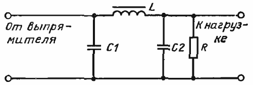
Consider an inductive input filter or an L-shaped LC filter. Its inclusion in the rectifier and the output voltage waveform are shown in Figure 3.
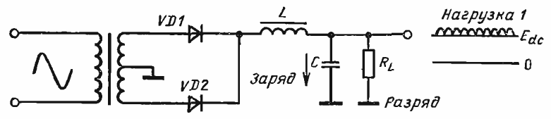
Rice. 3
Serial connection filter choke (L) with load inhibits current changes in the circuit. The output voltage here is less than with a capacitive input filter because the choke forms a series connection with an impedance formed by the parallel connection of the load and the filter capacitor. Such a connection leads to a good smoothing of the voltage wave acting at the input of the filter, improving the quality of the constant output voltage, although it reduces its value.
The AC component of the rectifier output voltage is almost completely isolated from the choke inductance, and the middle component is the supply output voltage. The presence of a choke leads to the fact that the duration of the conducting state of the rectifier diodes here, unlike the rectifier with a capacitive filter, is equal to half the period.
The choke reactance (L) reduces the value of the ripple voltage because it prevents the choke current from increasing when the rectifier output voltage is greater than the load voltage, and also prevents the current from decreasing if the output voltage of of the rectifier is less than the average value. Therefore, the current in the load during the period of operation is practically constant, and the voltage of the waves does not depend on the load current.
Multi-section inductive-capacitive filter
The filtering quality of the output voltage can be improved by connecting several filters in series. In fig. 4 shows a two-stage LC filter and roughly shows the voltage waveforms at different points on the filter relative to a common point.
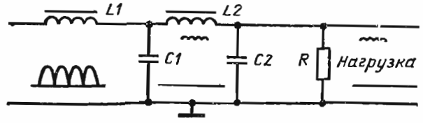
Rice. 4
Although two series-connected LC-filters are shown here, the number of connections can be increased. Increasing the number of connections leads to a decrease in ripple (and filters with many connections are used precisely when it is necessary to obtain a minimum ripple in the output voltage), but this reduces the stability of stabilizers with such filters. In addition, an increase in the number of connections leads to an increase in the resistance connected in series with the power supply, which leads to an increase in the changes in the output voltage with a change in the load current.
U-shaped filter
In fig. 5 shows a U-shaped filter, so called because its graphical representation resembles the letter P. It is a combination of capacitive and L-shaped LC-filters.
Rice. 5
A resistor R, which is connected to the output of the filter, is almost always present in power supplies and is optional load resistance… Its purpose is twofold.
First, it provides a discharge path for the capacitors when the mains voltage is interrupted and thus prevents the possibility of electric shock to service personnel.
Second, it provides an additional load on the power supply even when the external load is turned off and thus stabilizes the output voltage level. This resistor can also be used as an element resistive voltage divider for additional outputs.
The U-shaped filter is a filter with a capacitor input supplemented by an L-shaped connection.The main filtering action is performed by the capacitor C1, which is charged through the conducting diodes and discharged through L and R... As with a conventional filter with a capacitive input, the charging time of the capacitor is significantly shorter than the discharging time.
Choke L smoothes the ripples of the current flowing through the capacitor C2, providing additional filtering. The voltage across capacitor C2 is the output voltage. Although its value is slightly smaller than when feeding with a conventional capacitive filter, the ripple of the output voltage is significantly reduced.
Even if we assume that the capacitor C1 is charged through the conducting diodes of the rectifier to the value of the amplitude of the input AC voltage and then discharged through R, the voltage of the capacitor C2 will be less than that of C1, because the choke L, which prevents any changes in the load current, stands in the discharge circuit of the capacitor C1 and forms, together with C2 and R, a voltage divider.
The charging current of capacitors C1 and C2 passes through the secondary winding of the transformer and the conducting diodes of the rectifier. Also, when C2 is charged, this current flows through the choke L... Capacitor C1 discharges through series-connected L and R, and C2 discharges only through resistance R. The rate of discharge of input capacitor C1 depends on the value of resistance R.
The discharge time constant of the capacitors is directly proportional to the R value… If it is high, then the capacitors discharge a little and the output voltage is high.At lower values of R, the discharge rate increases and the output voltage will decrease, since decreasing R means increasing the discharge current of the capacitor. Thus, the lower the capacitor discharge time constant, the lower the average value of the output voltage.
U-shaped C-RC filter
Unlike the filter just discussed in the U-shaped C-RB C-filter, a resistor R is connected between the two capacitors instead of a choke.1 as shown in Fig. 6.
The main differences and filter performance are determined by the different choke response and AC resistance. In the previous case, the reactances of the inductor L and the capacitor C2 are such that the voltage divider formed by them provides a relatively better smoothing of the output voltage.
In fig. 6, both the DC and AC current components of the rectified current through R1. Due to the voltage drop across R1 from the DC component, the output voltage decreases and the greater the current, the greater this voltage drop. Therefore, the C-RC-filter can only be used with low load currents. As in the case of inductive-capacitive filters, it is possible to use a multi-level connection of filter circuits.
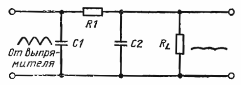
Rice. 6
Choosing filters in any case is not an easy problem, but in any case you need to understand their purpose and principles of operation due to the fact that they largely determine the correct operation of power supplies.