Push-in voltage converter
One of the most popular topologies of switching voltage converters is a push-pull converter or push-pull (literally, push-pull).
Unlike a single-cycle flyback converter, the energy in the pool-pool core is not stored, since in this case it is the core of the transformer and not throttle core, it serves here as a conductor for an alternating magnetic flux generated in turn by two halves of the primary winding.
Despite the fact that this is exactly a pulse transformer with a fixed transformation ratio, the stabilization voltage of the pulled-up output can still be changed by changing the width of the operating pulses (using pulse width modulation).
Due to their high efficiency (efficiency up to 95%) and the presence of galvanic isolation of the primary and secondary circuits, push-pull switching converters are widely used in stabilizers and inverters with a power of 200 to 500 W (power supplies, car inverters, UPS, etc. .)
The figure below shows a general schematic of a typical push-pull converter.The primary and secondary windings have middle taps, so that in each of the two operating half-cycles when only one of the transistors is active, its own half of the primary winding and the corresponding half of the secondary winding will be turned on, where the voltage will drop to only one of the two diodes.
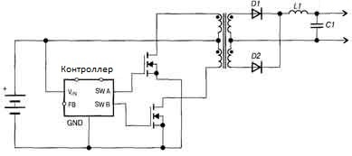
The use of a full-wave rectifier with Schottky diodes at the output of a push-down converter makes it possible to reduce active losses and increase efficiency, since it is economically more expedient to wind two halves of the secondary winding than to absorb the losses ( financial and active ) with a diode bridge of four diodes.
The switches in the primary loop of a push-pull converter (MOSFET or IGBT) must be rated for double supply voltage to withstand the action of not only the source EMF, but also the additional EMF action induced during operation of each other.
The device characteristics and mode of operation of the push-pull circuit compare favorably with a half-bridge, forward and reverse. Unlike a half bridge, there is no need to decouple the switch control circuit from the input voltage. The converter mechanism works as two pull-forward converters in one device.
Also, unlike the forward one, the buck-pull-down converter does not need a limiting coil because one of the output diodes continues to conduct current even with the transistors closed. Finally, unlike the inverse converter, the push button and magnetic circuit are used more sparingly, and the effective pulse duration is longer.
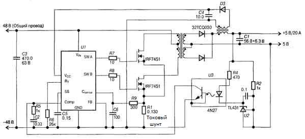
Push-pull current control circuits are becoming increasingly popular in embedded power supplies for electronic devices. With this approach, the problem of increased stress on the keys is completely eliminated. A shunt resistor is included in the common source circuit of the switches from which the feedback voltage is removed for current protection. Each switch operation cycle is limited in duration from the moment the current reaches the specified value. Under load, the output voltage is usually limited by PWM.
In the design of a push-pull converter, special attention is paid to the selection of switches so that the open channel resistance and gate capacitance are as low as possible. To control the gates of field-effect transistors in a push-pull converter, gate driver microcircuits are most often used, which easily cope with their task even at frequencies of hundreds of kilohertz, characteristic of pulsed power supplies of any topology.