Buck Converter — component sizing
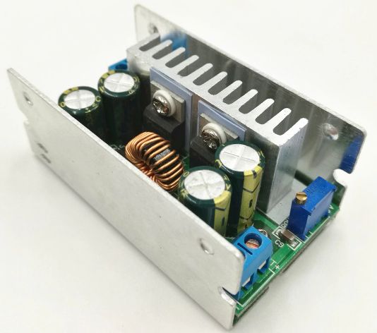
This article will give the procedure for calculating and selecting the components needed to design the power section of a galvanically isolated step-down DC converter, buck converter topology. Converters of this topology are suitable for step-down DC voltages within 50 volts at the input and at load powers not exceeding 100 watts.
Everything that concerns the selection of the controller and driver circuit, as well as the type of field-effect transistor, will be left outside the scope of this article, but we will analyze in detail the circuit and the characteristics of the operating modes of each of the main components of the power section of converters of this type.
Start development pulse converter, take into account the following initial data: the input and output voltage values, the maximum constant load current, the switching frequency of the power transistor (the operating frequency of the converter), as well as the current wave through choke Also, based on these data, calculate choke inductance, which will provide the necessary parameters, the capacity of the output capacitor, as well as the characteristics of the reverse diode.
-
Input voltage — Uin, V
-
Output voltage — Uout, V
-
Maximum load current — Iout, A
-
Range of ripple current through the choke — Idr, A
-
Switching frequency of transistors — f, kHz
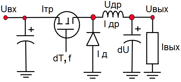
The converter works as follows. During the first part of the period when the transistor is closed, current is supplied from the primary power source through the inductor to the load while the output filter capacitor is charging. When the transistor is open, the load current is maintained by the capacitor charge and the inductor current, which cannot be interrupted immediately, and is closed by the reverse diode, which is now open during the second part of the period.
For example, let's say that we need to develop a topology of a buck converter powered by a constant voltage of 24 volts, and at the output we need to get 12 volts with a rated load current of 1 amp and so that the voltage ripple at the output does not exceed 50 mV. Let the operating frequency of the converter be 450 kHz, and the current ripple through the inductor does not exceed 30% of the maximum load current.
Initial data:
-
Uin = 24 V
-
Uout = 12V
-
I out = 1 A.
-
I dr = 0.3 * 1 A = 0.3 A
-
f = 450 kHz
Since we are talking about a pulse converter, during its operation the voltage will not be applied constantly to the choke, it will be applied precisely by pulses, the duration of the positive parts of which dT can be calculated based on the operating frequency of the converter and the ratio of the input and output voltage according to the following formula:
dT = Uout / (Uin * f),
where Uout / Uin = DC is the duty cycle of the transistor control pulse.
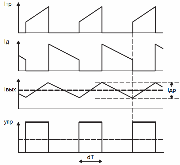
During the positive part of the switching pulse, the source powers the converter circuit, during the negative part of the pulse, the energy stored by the inductor is transferred to the output circuit.
For our example, it turns out: dT = 1.11 μs — the time that the input voltage acts on the inductor with the capacitor and the load connected to it during the positive part of the pulse.
According to with the law of electromagnetic induction, the change in the current Idr through the inductor L (which is the choke) will be proportional to the voltage Udr applied to the terminals of the coil and the time of its application dT (duration of the positive part of the pulse):
Udr = L * Idr / dT
The choke voltage Udr — in this case nothing more than the difference between the input and output voltages during that part of the period when the transistor is in the conducting state:
Udr = Uin-Uout
And for our example it turns out: Udr = 24 — 12 = 12 V — the amplitude of the voltage applied to the choke during the positive part of the operating pulse.
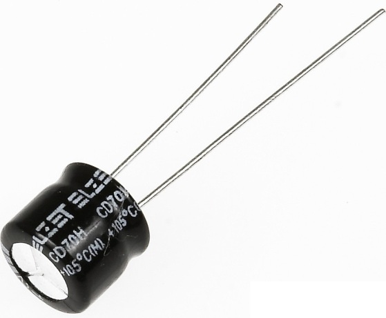
Throttle
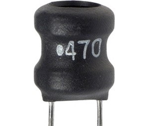
Now, knowing the magnitude of the voltage applied to the choke Udr, setting the time of the operating pulse dT on the choke, as well as the value of the maximum permissible current ripple of the choke Idr, we can calculate the required choke inductance L:
L = Udr * dT / Idr
For our example, it turns out: L = 44.4 μH — the minimum inductance of the working choke, with which, for a given duration of the positive part of the control pulse dT, the swing of the wave will not exceed Idr.
Condenser
When the value of the inductance of the choke is determined, proceed to the selection of the capacitance of the output capacitor of the filter. The ripple current through the capacitor is equal to the ripple current through the inductor. Therefore, neglecting the resistance of the inductive conductor and the inductance of the capacitor, we use the following formula to find the minimum required capacitance of the capacitor:
C = dT * Idr / dU,
where dU is the voltage ripple across the capacitor.
Taking the value of the voltage wave in the capacitor equal to dU = 0.050 V, for our example we get C = 6.66 μF — the minimum capacitance of the output capacitor of the filter.
Diode
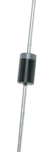
Finally, it remains to determine the parameters of the working diode. The current flows through the diode when the input voltage is disconnected from the inductor, that is, in the second part of the operating pulse:
Id = (1 -DC) * Iout — average current through the diode when it is open and conducting.
For our example Id = (1 -Uout / Uin) * Iout = 0.5 A — you can choose a Schottky diode for a current of 1 A with a maximum reverse voltage greater than the input, that is, about 30 volts.