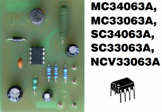
Chip MC34063A / MC33063A-boost (buck) pulse converter without galvanic isolation on one chip
Today we will consider such a wonderful microcircuit as the MC34063 (MC33063), which is an integrated microcontroller of a pulse voltage converter without galvanic isolation and requires a minimum of external components for the full operation of the one built on its basis miniature DC-DC converter (buck, boost or flip).
We immediately note that the maximum operating current for the built-in power switch of this microcircuit should not exceed 1.5 amperes, and the maximum input voltage for it is not less than 40 volts at the minimum possible 3.3 V.
Unlike the 78xx series linear regulators, the switching DC-DC converter has higher efficiency, does not require a heatsink and, designed for a specific output power, takes up very little PCB space.
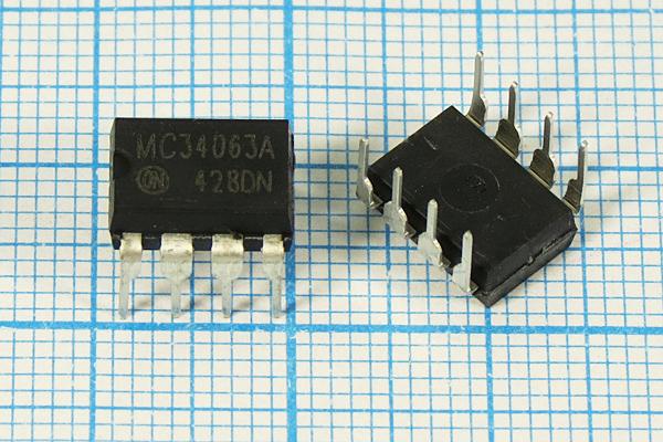
The MC34063 chip (MC33063) is available in both lead and flat packages. In the company data sheet ON Semiconductor the following schematic diagram of this component is shown:
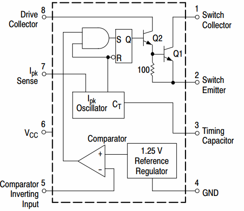
Conclusions 6 and 4 — power supply
The internal functional blocks of the chip are powered by DC voltage through pins 6 and 4. The fourth pin is common (GND), the sixth pin is the power supply positive (Vcc) for both the chip and a small external circuit that will be assembled around it.
Findings 3, 4 and 7
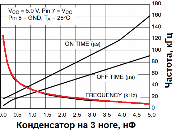
The built-in oscillator of the microcircuit generates rectangular pulses with a constant frequency, the value of which is determined by the capacitance of the capacitor connected between pins 3 and 4, and the duration of each pulse depends on the voltage at pin 7 — of a resistive current sensor. As soon as the voltage on pin 7 reaches 0.3 V, the control square wave pulse inside the microcircuit is completed. In addition, it will become clear why this happens.
The conclusion is that between pins 6 and 7, according to the requirements of the documentation for this microcircuit, an external current limiting resistor must be installed. In addition, the maximum voltage of this resistor determines the point of maximum current of the operating external circuit at each subsequent pulse.
In accordance with Ohm's law, the maximum 1.5 amps of current at 0.3 volts (this is the microcircuit calibration according to the datasheet) of the resistor is achievable with a resistor rated at 0.2 ohms. However, some margin is always needed, so they take up a minimum of 0.25 Ohm — usually four 1 Ohm resistors in parallel at this point.
Conclusion 8
Pin 8 is the open collector of the internal transistor Q2, which drives the power transistor Q1, which is designed to switch the external inductance to the power supply. The total current gain here is in the region of 75.This means that depending on the topology of the designed converter, a resistor on pin 8 may be needed to limit the base current.
Conclusion 5
Due to the presence of a calibrated reference voltage source of 1.25 volts built into the microcircuit, in the designed DC-DC converter of any topology, you can easily build the most common output voltage feedback loop. Namely — to apply from the output of the converter, through a resistive divider, to pin No. 5, the corresponding voltage of 1.25 volts, making up a certain part of the required output voltage.
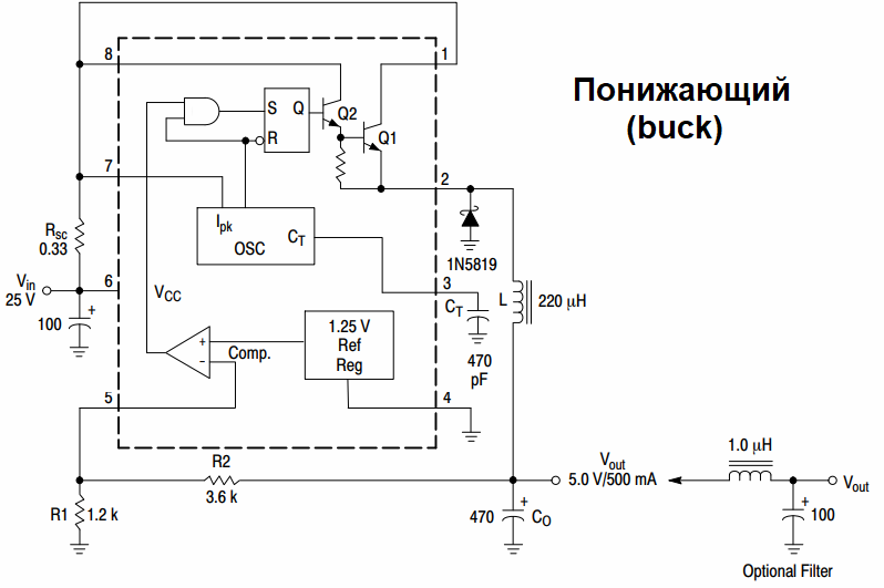
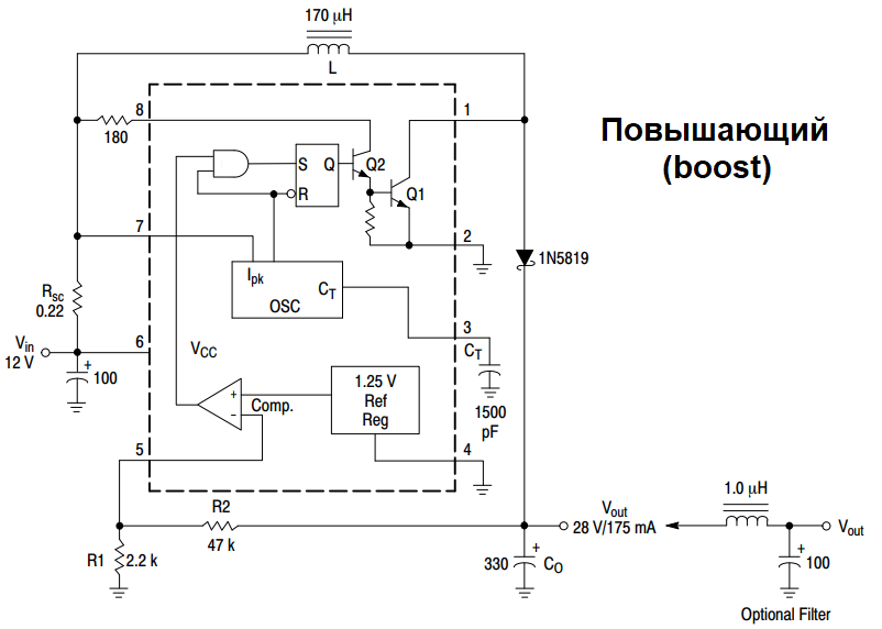
Since the principles of construction converters such as Buck and Boost we have already analyzed in previous articles, now we will not dwell on these principles in detail, but only note that in addition to the microcircuit itself, to build a Buck (lowering) or Boost (increasing) converter without galvanic isolation of the microcircuit MC34063 (MC33063), except for the chip itself, which we only need Schottky diode type 1N5822 or 1N5819, depending on the output current, a choke of suitable inductance and suitable maximum current, a few resistors to provide a 0.25 ohm shunt and for a total power dissipation of about 1-2 W, a 3x sync capacitor, and output capacitor filter and capacitor at the input of the 6th leg (electrolytic).
See also:Buck Converter — Component sizing