Operating modes of electric drives in speed and torque coordinates
Most of the generated electrical energy is converted into mechanical energy using an electric drive to ensure the operation of various machines and mechanisms.
One of the important tasks electric drive is determination of the necessary law of change in the moment M of the engine under a certain load and the necessary nature of the motion given by the law of change of acceleration or velocity. This task boils down to the synthesis of an electric drive system that provides a set law of motion.
In the general case, the signs of the moments M (motor torque) and Ms (moment of resistance forces) may be different.
For example, with the same signs M and Mc, the drive operates in motor mode with increasing speed w (angular acceleration e> 0).In this case, the rotation of the drive occurs in the direction of application of the torque M of the motor, which can act in either of two possible directions (clockwise or counterclockwise).
One of these directions, for example clockwise, is taken as positive, and when the drive rotates in that direction, the moment M and the velocity w are considered positive. In the moment and velocity coordinate system (M, w), such a mode of operation will be located in the I quadrant.
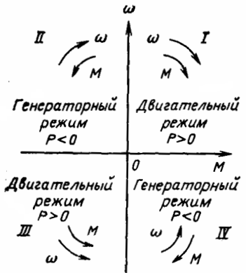
Regions of operation modes of the electric drive in the coordinates of the speed w and the moment M
If, with a stationary drive, the direction of action of the torque M changes, then its sign will become negative, and the value e (angular acceleration of the drive)<0. In this case, the absolute value of the speed w increases, but its sign is negative, that is, the drive accelerates in motor mode when it rotates counterclockwise. This regime will be located in the III quadrant.
The direction of the static moment Mc (or its sign) depends on the type of resistance forces acting on the working body and the direction of rotation.
Static moment is created by beneficial and harmful resistance forces. The resistance forces that the machine is designed to overcome are useful. Their size and nature depend on the type of production process and the design of the machine.
Harmful resistance forces are caused by various types of losses occurring in mechanisms during movement, and when overcome, the machine does no useful work.
The main cause of these losses is the frictional forces in the bearings, gears, etc., which always impede movement in any direction. Therefore, when the sign of the velocity w changes, the sign of the static moment Mc, due to the indicated resistance forces, changes.
Such static moments are called reactive or passive, because Onito always hinder movement, but under their influence, when the engine is turned off, movement cannot occur.
Static moments created by useful resistance forces can also be reactive if the operation of the machine involves overcoming the forces of friction, cutting or tension, compression and torsion of inelastic bodies.
However, if the production process carried out by the machine is associated with a change in the potential energy of the elements of the system (load lifting, elastic deformations of torsion, compression, etc.), then the static moments created by useful resistance forces are called potential or active.
Their direction of action remains constant and the sign of the static moment Mc does not change when the sign of the velocity o changes. In this case, as the potential energy of the system increases, the static moment prevents movement (for example, when lifting a load), and when it decreases, it promotes movement (lowering a load) even when the engine is turned off.
If the electromagnetic moment M and the speed o are directed oppositely, then the electric machine works in the stop mode, which corresponds to the II and IV quadrants. Depending on the ratio of the absolute values of M and Mc, the rotational speed of the drive can increase, decrease or remain constant.
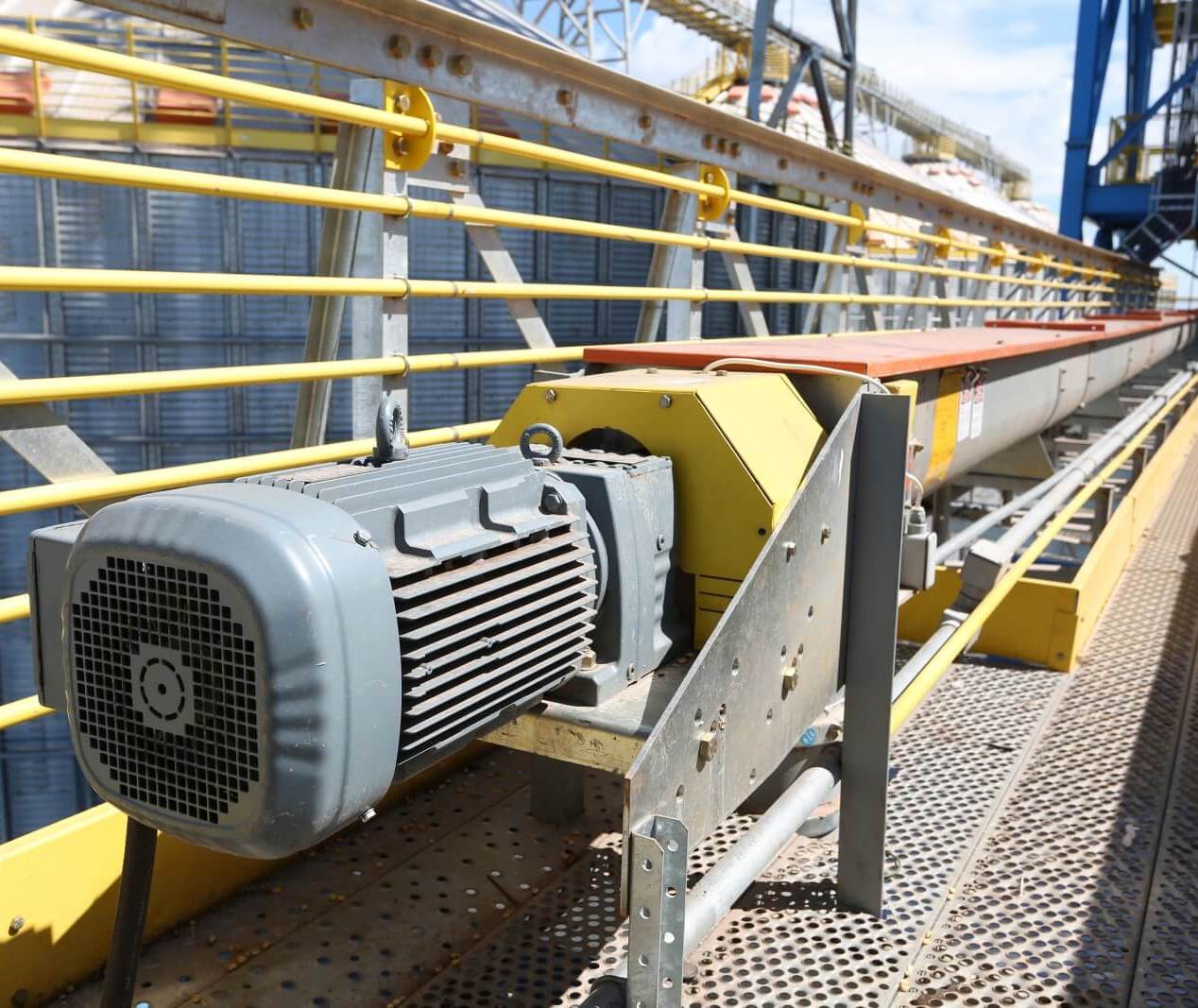
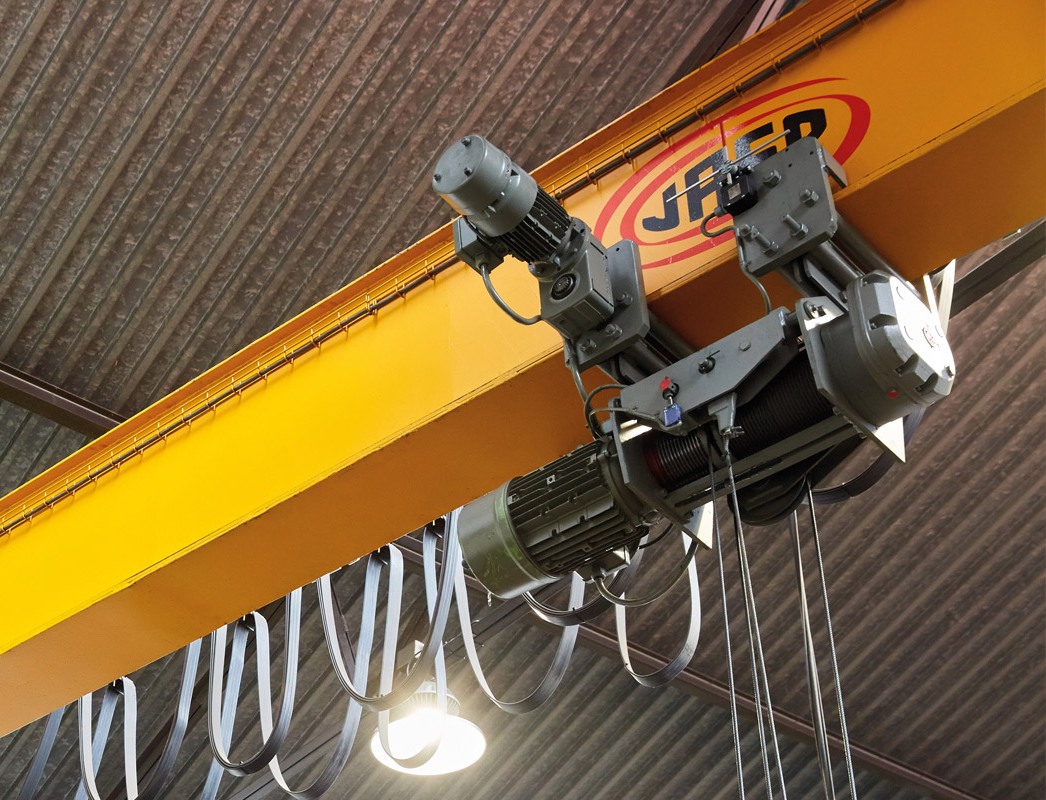
The purpose of an electric machine used as a prime mover is to supply the working machine with mechanical energy to do work or to stop the working machine (for example, Choice of electric drive for conveyors).
In the first case, the electrical energy supplied to the electric machine is converted into mechanical energy, and a torque is generated on the shaft of the machine, which ensures the rotation of the drive and the performance of useful work by the production unit.
This mode of operation of the electric drive is called motor… Motor torque and speed match in direction, and motor shaft power P = Mw > 0.
The characteristics of the motor in this mode of operation can be in I or III quadrant, where the signs of the speed and torque are the same and therefore P> 0. The choice of the sign of the speed with a known direction of rotation of the motor (right or left) can to be arbitrary.
Usually, the positive direction of speed is taken to be the direction of rotation of the drive in which the mechanism performs the main work (for example, lifting a load with a lifting machine). Then the operation of the electric drive in the opposite direction occurs with a negative sign of the speed.
To slow down or stop the machine, the engine can be disconnected from the mains. In this case, the speed decreases under the action of the forces of resistance to the movement.
This mode of operation is called free movement… In this case, at any speed, the torque of the drive is zero, that is, the mechanical characteristic of the motor coincides with the ordinate axis.
To reduce or stop speed more quickly than in free take-off, and to maintain a constant speed of the mechanism with a load torque acting in the direction of rotation, the direction of the moment of the electric machine must be opposite to the direction of speed .
This mode of operation of the device is called inhibitory, while the electric machine is operating in generator mode.
Driving power P = Mw <0, and the mechanical energy from the working machine is fed to the shaft of the electric machine and converted into electrical energy. Mechanical characteristics in generator mode are found in quadrants II and IV.
The behavior of the electric drive, as follows from the equation of motion, with the given parameters of the mechanical elements is determined by the values of the moments of the motor and the load on the shaft of the working body.
Since the speed change law of an electric drive during operation is most often analyzed, it is convenient to use a graphical method for electric drives in which the motor torque and the load torque depend on the speed.
For this purpose, the mechanical characteristic of the motor is usually used, which represents the dependence of the angular speed of the motor on its torque w = f (M), and the mechanical characteristic of the mechanism, which establishes the dependence of the motor speed on the reduced static moment created by the load of the work element w = f (Mc) …
The specified dependences for steady-state operation of the electric drive are called static mechanical characteristics.
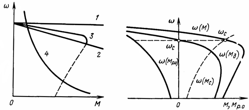
Static mechanical characteristics of electric motors