The principle of operation of the generator
Generators are machines converting mechanical energy into electrical energy… The principle of operation of the generator is based on the phenomenon of electromagnetic induction, when an EMF is induced in a conductor moving in a magnetic field and crossing its magnetic forces. Therefore, such a conductor can be considered by us as a source of electrical energy.
The method of obtaining induced EMF, in which the wire moves in a magnetic field, moving up or down, is very inconvenient for its practical use. Therefore, in generators, not rectilinear, but rotational movement of the wire is used.
The main parts of any generator are: a system of magnets, or more often electromagnets, creating a magnetic field, and a system of wires crossing this magnetic field.
Let's take a wire in the form of a curved loop, which we will further call a frame (Fig. 1), and place it in a magnetic field created by the poles of a magnet. If such a frame is given a rotational motion about the 00 axis, then its sides facing the poles will cross the magnetic field lines and an EMF will be induced in them.
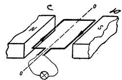
Rice. 1. EMF induction in a bell-shaped conductor (frame) rotating in a magnetic field
By connecting a light bulb to the frame using soft wires, in this way we will close the circuit and the light will light up. The light bulb will continue to burn while the frame rotates in a magnetic field. Such a device is the simplest generator, which converts the mechanical energy spent on the rotation of the frame into electrical energy.
Such a simple generator has a rather significant drawback. After a short period of time, the soft wires connecting the bulb to the rotating frame will twist and break. To avoid such interruptions in the circuit, the ends of the frame (Fig. 2) are attached to two copper rings 1 and 2, which rotate together with the frame.
These rings are called slip rings. The electric current is diverted from the slip rings to the outer circuit (to the bulb) via elastic plates 3 and 4 adjacent to the rings. These plates are called brushes.
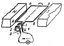
Rice. 2. The direction of the induced EMF (and current) in wires A and B of the frame rotating in a magnetic field: 1 and 2 — slip rings, 3 and 4 — brushes.
With such a connection of the rotating frame to the external circuit, the disconnection of the connecting wires will not occur and the generator will operate normally.
Let us now consider the direction of the EMF induced in the frame leads, or, which is the same, the direction of the current induced in the frame with the external circuit closed.
With the direction of rotation of the frame, which is shown in fig. 2, in the left conductor AA, the EMF will be induced in a direction from us out of the plane of the drawing, and in the right explosive - due to the plane of the drawing on us.
Since the two halves of the frame wire are connected in series with each other, the induced EMF in them will increase, and on brush 4 there will be a positive pole of the generator and a negative pole of brush 3.
Let us trace the change in the induced EMF as the frame rotates completely. If the clockwise frame is rotated 90° from the position shown in Fig. 2, then the halves of its conductor at that moment will move along the magnetic field lines and the induction of EMF in them will stop.
Further rotation of the frame by another 90 ° will lead to the fact that the wires of the frame will again cross the lines of force of the magnetic field (Fig. 3), but the wire AA will move with respect to the lines of force not from the bottom up, but from above down, while the wire BB on the contrary, it will cross the lines of force, moving from the bottom up.
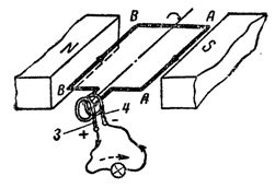
Rice. 3. Changing the direction of the induced e. etc. s. (and current) when the frame is rotated 180 ° with respect to the position shown in fig. 2.
With a new position of the frame, the direction of the induced emf in wires AL and BB will change in the opposite direction. This follows from the fact that the very direction in which each of these wires crosses the magnetic field lines in this case has changed. As a result, the polarity of the generator brushes will also change: brush 3 will now become positive, and brush 4 negative.
Turning the frame further, we will again have the movement of wires AA and BB along the magnetic force lines, and in the future - the repetition of all processes from the beginning.
Thus, during one complete rotation of the frame, the induced EMF changes its direction twice, and its value during the same time also reaches its highest values twice (when the wires of the frame pass under the poles) and twice equal to zero (in the moments of movement of the wires along the magnetic field lines).
It is quite clear that an EMF that changes in direction and magnitude will induce an electric current that changes in direction and magnitude in a closed external circuit.
So, for example, if a light bulb is connected to the terminals of this simplest generator, then during the first half of the rotation of the frame, the electric current through the bulb will go in one direction, and during the second half of the turn, in the other.
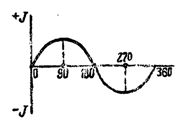
Rice. 4. Curve of change of the induced current for one revolution of the frame
The curve in fig. 1 gives an idea of the nature of the current change when the frame is rotated 360 °, that is, in one complete revolution. 4. An electric current is induced, continuously changing in magnitude and direction alternating current.