How to connect an induction motor
An induction motor is an alternating current motor whose rotor speed differs from the speed of the magnetic field generated by the current in the stator winding. Asynchronous engine converts electrical energy into mechanical energy… Due to the simplicity of design, reliability in operation, motors of this type are the most common electric machines in the world.
Look: The device and principle of operation of asynchronous motors,
and Asynchronous motors with a wound rotor, Single-phase and two-phase asynchronous motors
The phase windings of the stator of the electric motor are connected in star or delta (depending on the mains voltage). If in the passport of the electric motor it is indicated that the windings are made for a voltage of 220/380 V, then when it is connected to a network with a network voltage of 220 V, the windings are connected in a triangle, and when connected to a 380 V network, in a star.
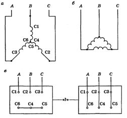
Connection diagrams of the stator windings of a three-phase asynchronous motor: a — in a star, b — in a delta, c — in a star and a delta on the terminal board of the electric motor
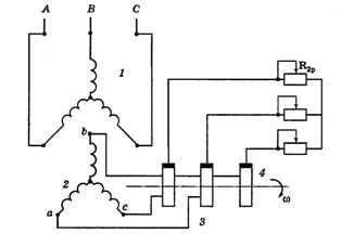
Circuit diagram of an asynchronous electric motor with a phase rotor: 1 — stator winding, 2 — rotor winding, 3 — slip rings, 4 — brushes, R — resistors.
To change the direction of rotation of the induction motor shaft, it is necessary to change the direction of rotation of the magnetic field of the stator. To do this, it is enough to replace all two wires connecting the stator winding to the mains.
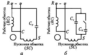
Connection diagram of single-phase capacitor motors: a — with working capacity Cp, b — with working capacity Cp and starting capacity Cp.
See also:
Schemes for turning on an induction motor with a magnetic starter