Electric drive with asynchronous valve cascade
 In industry, a drive with a shallow speed adjustment range (3:2:1) is used, that is, the so-called valve cascade, built on the basis of an asynchronous electric motor and representing a system of adjustable variable drive.
Unlike throttle and frequency regulation, with a cascade connection, an asynchronous electric motor is connected to a three-phase alternating current supply network. This is a big advantage of this drive system over the first two. It also has a higher efficiency than all other systems. This advantage can be explained by the fact that in cascade systems only the slip energy is converted, while in DC drives and variable frequency systems, the entire amount of energy consumed by the motor is subject to conversion.
Compared to throttle and rheostat actuators, as well as slip clutches, where the slip energy is lost by them in resistances, the advantages of the valve cascade in terms of energy are even higher.The converters in the rotor circuit of these systems serve only for speed control. The drive, built using an asynchronous motor, allows you to create high-speed systems with variable power. Such systems provide smooth speed and torque control, do not require a large number of power and contact equipment.
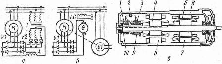
Rice. 1. Schemes of cascades: a — valve, b — valve machine, c — single-body valve machine
The valve cascade also has low control power, is easily automated and has good dynamic properties.
It should be noted that in the valve cascade, the frequency converter of the rotor circuit does not circulate reactive power to create a rotating magnetic flux of the induction motor, since this flux is created by reactive power entering the stator circuit.
In addition, the converter used in the valve stage is only designed for power proportional to the given control range. At the same time, in systems with frequency control, the converter is involved in the creation of magnetic flux, and in its design it is necessary to take into account the full power of the drive. The simplest valve stage circuit is a circuit with an intermediate DC circuit and a valve EMF converter.
In valve circuits (Fig. A) and valve-machine cascades (Fig. B), the rotor current is rectified according to a three-phase bridge circuit, and an additional EMF is introduced into the rectified current circuit in the first housing by the valve converter, and in the second — from the DC machine. The circuit shown in fig. a, consists of an induction motor M with a phase rotor.
A valve converter V1 is included in the rotor circuit, in which the rotor AC current is rectified.With a valve converter, an inverter (valve converter V2) is switched on through the throttle L, which is a source of additional EMF. The valve converter V2 is assembled with a transformer T according to a three-phase neutral circuit. Usually used in small devices.
In this diagram, the functions of the two valve converters are clearly delineated. Here the VI valves act as rectifiers, converting the slip frequency rotor alternating current to direct current. Valves V2 convert the current of the standing rotor into alternating current at the frequency of the network, that is, they work in the mode of a dependent inverter.
In the valve-machine cascade (Fig. C), the conversion of the rotor current rectified by the valve converter V1 into an alternating current with the frequency of the network takes place with the help of a direct current machine G and a synchronous generator G1. In this circuit, machines G and G1 play the role of an inverter.
Various schemes of asynchronous valve cascades have been developed, but the basic and most common scheme is shown in Fig. Of interest are the AMVK-13-4 single enclosures with a power of 13 kW. In one case, an induction motor with a phase rotor, a DC machine and a rotor group of uncontrolled valves are placed on such a cascade.
The device is an AC motor with stepless speed regulation. These devices can overcome significant overloads. The cascade has a nominal speed of 1400 min-1, a supply voltage of 380 V and an adjustment range of 1400-650 min-1 without switching the stator circuit.
When switching the stator winding from star to delta, the control range will be 1400-400 min-1, the torque is constant, the weight of the unit is 360 kg, the excitation voltage is 220 V.The device has a protected blown construction. These units are applicable in drive units.
A schematic arrangement of a valve-machine cascade with one body is shown in Fig. v. Rotor 5 of an asynchronous electric motor and armature 4 of a DC machine are mounted on one shaft. In a common steel cylindrical bed 6, the stator 7 of the asynchronous electric motor and the poles 8 of the DC machine are mounted. Collector 9 and sliding rings 10, collector brushes 3 and brushes 1 of the asynchronous motor are connected through silicon rectifiers 2. To remove heat from the machine, especially at reduced speed, there are special ventilation channels in the rotor and in the frame.
The bridge rectifier supplying the rectified rotor voltage to the DC machine armature is assembled from six VK-50-1.5 valves with a reverse voltage of 150 V. where energy saving is essential.
Along with the described advantages of the considered systems, it is necessary to note their disadvantages: the high cost of the valve converters and the valve-machine drive, low power factor, low efficiency compared to an asynchronous motor due to the fact that the drive works with maximum speed without short circuit of the rotor winding motor, low overload capacity of the induction motor, low use of the drive motor (by about 5-7%), the need for special starting means that provide starting characteristics with shallow speed control.