Electromechanical properties of DC motors
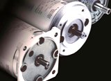 DC motors with stepless speed regulation are used in drives of various machines, metal cutting machines and plants. Along with the wide range of speed control, they make it possible to obtain mechanical characteristics with different (required) stiffness.
It is known from the course of electrical engineering that the equation of mechanical characteristics [n = f (M)] can be written as
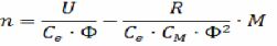
where the coefficients Ce and Cm depend on the design data of the engine; U is the line voltage; F is the magnetic flux of the motor; R is the armature circuit resistance.
The formula shows that if U, R and F are constant, the mechanical characteristic of the parallel excitation motor is a straight line (Fig.). If there are no resistances in the armature circuit, then the mechanical characteristic is natural (straight line 1, Fig. A). Point A corresponds to the nominal speed nNa but is called the ideal idle frequency.The stiffness of the characteristic is determined by the resistance of the motor R ', which includes the resistance of the armature winding, additional poles, compensation winding, brushes. The influence of the resistance in the armature circuit on the characteristic is illustrated by straight lines 2 and 3 (see Fig. A).
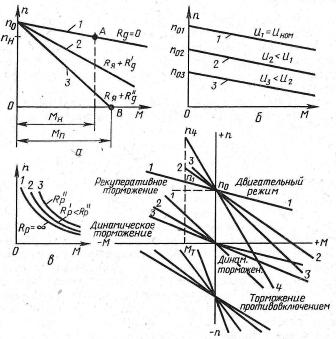
Rice. 1. Mechanical characteristics of DC motors: a — when the resistance in the rotor circuit changes, b — when the voltage in the armature of the DC motor circuit with a change of independent excitation changes, c — when the speed of rotation is controlled by maneuvering the the excitation winding of the motor with series excitation, d — with different braking modes.
The formula makes it possible to estimate the influence of voltage U and flux F. When U changes, the mechanical characteristic of a motor with independent excitation is shifted parallel to the natural one (Fig. C); the idle speed at constant R and U varies inversely with the flow.
From the formula for n = 0 we have
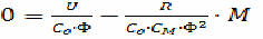
i.e. the starting torque is proportional to the flux.
Thus, the speed of the motor can be adjusted by varying the magnetic flux, the voltage applied to the armature winding, by introducing resistances in the armature circuit.
Regulating engine speed by changing F is used quite often, as the regulation is smooth, without large energy losses, subject to automation. The range of adjustment in the direction of increasing the rotation frequency does not exceed 1: 4, it can be expanded by introducing a small stabilizing winding of series excitation together with the winding of additional poles.
Regulating the speed of rotation by changing the voltage applied to the armature circuit of the motor is widely used in an independently excited motor (Fig. C). Currently, motors are produced with a regulation range of up to 1: 8, the range increases when using thyristor converters.
See on this topic: Parallel Excitation Motor Braking Modes