Starting, reversing and stopping DC motors
 Starting a DC motor, connecting it directly to the mains voltage is only permissible for low power motors. In this case, the peak current at the beginning of the start can be of the order of 4 - 6 times the nominal. Direct starting of DC motors with significant power is completely unacceptable, since the starting current here will be equal to 15 - 50 times the rated current. Therefore, the starting of medium and large power motors is carried out using a starting rheostat, which limits the current during starting to the values permissible for commutation and mechanical strength.
Run rheostats made of high resistance wire or tape divided into sections. The wires are connected to copper buttons or flat contacts at the transition points from one section to another. The copper brush on the rotating arm of the rheostat moves along the contacts. Rheostats can have other designs.The excitation current at the start of the parallel-excitation motor is set corresponding to normal operation, the excitation circuit is connected directly to the mains voltage, so that there is no voltage drop due to the voltage drop in the rheostat (see Fig. 1).
The need for a normal excitation current is due to the fact that when starting the motor, the largest possible permissible torque Mem must be developed, which is necessary to ensure rapid acceleration. Starting a DC motor is done by successively reducing the resistance of the rheostat, usually by moving the rheostat lever from one fixed contact of the rheostat to another and turning the sections off; resistance reduction can also be done by short-circuiting the sections with contactors that are activated according to a given program.
When starting manually or automatically, the current changes from a maximum value equal to 1.8 - 2.5 times the nominal value at the beginning of operation for a given resistance of the rheostat to a minimum value equal to 1.1 - 1.5 times the nominal value at the end in operation and before switching to another position of the starting rheostat. The armature current after starting the motor with rheostat resistance rp is
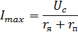
where Uc is the line voltage.
After switching on, the motor starts to accelerate until back emf E occurs and the armature current decreases. Given that the mechanical characteristics n = f1 (Mн) and n = f2 (II am) are practically linear, then during acceleration there will be an increase in the speed of rotation according to a linear law depending on the armature current (Fig. 1).
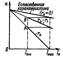
Rice. 1. DC motor starting diagram
The starting diagram (Fig.1) for different resistances in the armature is a segment of linear mechanical characteristics. When the armature current IХ decreases to the value Imin, the rheostat section with resistance r1 is turned off and the current increases to the value
where E1 — EMF at point A of the characteristic; r1 — resistance of the disconnected section.
The motor is then accelerated again to point B and so on until it reaches the natural characteristic when the motor is switched directly to the voltage Uc. The starting rheostats are designed to heat up for 4-6 starts in a row, so you need to make sure that at the end of the start the starting rheostat is completely removed.
When stopped, the motor is disconnected from the power source and the starting rheostat turns on fully — the motor is ready for the next start. To eliminate the possibility of large self-induction EMFs when the excitation circuit is broken and when it is disconnected, the circuit can be closed to the discharge resistance.
In variable speed drives, DC motors are started by gradually increasing the voltage of the power source so that the starting current is maintained within the required limits or remains approximately constant for most of the starting time. The latter can be done by automatically controlling the process of changing the voltage of the power source in feedback systems.
Starting DC motors with series excitation also manufactured using starters. The start-up diagram represents the segments of the nonlinear mechanical characteristic for different armature resistances.Starting at relatively low powers can be done manually, and at high powers by short-circuiting the sections of the starting rheostat with contactors that are triggered when operated manually or automatically.
Reversing — changing the direction of rotation of the engine — is done by changing the direction of the torque. To do this, it is necessary to change the direction of the magnetic flux of the DC motor, that is, to switch the field or armature winding, while the current in the other direction will flow in the armature. When switching both the excitation circuit and the armature, the direction of rotation will remain the same.
The field winding of a parallel-field motor has a significant energy reserve: the winding time constant is seconds for high-power motors. The time constant of the armature winding is much shorter. Therefore, in order to make the turn as quickly as possible, the anchor is switched. Only where no speed is required can reversal be effected by switching the excitation circuit.
Reversible excitation of motors can be done by switching either the field winding or the armature winding, since the energy reserves in the field and armature windings are small and their time constants are relatively small.
When reversing a parallel excitation motor, the armature is first de-energized and the motor is mechanically stopped or switched to stop. After the end of the delay, the armature is switched, if it was not engaged during the delay, and a start is made in the other direction of rotation.
Reversing a series-excitation motor is done in the same sequence: shut down — stop — switch — start in the other direction. In mixed-excitation motors in reverse, the armature or series winding must be switched along with the parallel.
Braking is necessary to reduce the run-out time of the motors, which in the absence of braking can be unacceptably long, and to fix the actuators in a certain position. Mechanical braking DC motors are usually manufactured by placing the brake pads on the brake disc. The disadvantage of mechanical brakes is that the braking moment and braking time depend on random factors: the penetration of oil or moisture into the brake disc and others. Therefore, such braking is used when time and stopping distance are not limited.
In some cases, after preliminary electrical braking at low speed, it is possible to precisely stop the mechanism (for example, lifting) in a given position and fix its position in a certain place. Such a stop is also used in emergency situations.
Electric braking provides sufficiently accurate obtaining of the necessary braking moment, but cannot ensure the fixing of the mechanism in a given place. Therefore, the electrical braking, if necessary, is supplemented by a mechanical braking, which takes effect after the end of the electrical.
Electrical braking occurs when current flows according to the EMF of the motor. There are three ways to stop.
Braking DC motors with energy return to the grid.In this case, the EMF E must be greater than the voltage of the power source US and the current will flow in the direction of the EMF, being the mode current of the generator. The stored kinetic energy will be converted into electrical energy and partially returned to the grid. The connection diagram is shown in fig. 2, a.
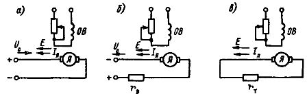
Rice. 2. Schemes of electric braking of DC motors: I — with energy return to the network; b — with opposition; c — dynamic braking
Stopping the DC motor can be done when the supply voltage decreases so that Uc <E, as well as when the loads in a hoist are lowered and in other cases.
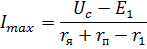
Reverse braking is done by switching the rotating motor in the opposite direction of rotation. In this case, the EMF E and the voltage Uc in the armature are added, and to limit the current I, a resistor with an initial resistance must be included

where Imax is the highest allowable current.
Stopping is associated with large energy losses.
Dynamic braking of DC motors is carried out when the resistor rt is connected to the terminals of the rotating excited motor (Fig. 2, c). The stored kinetic energy is converted into electrical energy and dissipated in the armature as heat. This is the most common suspension method.
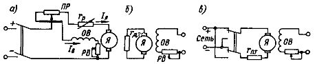
Circuits for switching on a DC motor with parallel (independent) excitation: a — motor switching circuit, b — switching circuit during dynamic braking, c — opposition circuit.