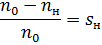
Generator system — DC motor
 Various machine tools often require stepless control of drive speed over a wider range than can be provided by adjusting the magnetic flux. DC motor with parallel excitation… In these cases, more complex electric drive systems are used.
In fig. 1 shows a diagram of an adjustable electric drive according to a generator-motor system (abbreviated G — D). In this system, an induction motor IM continuously rotates an independently excited DC generator G and an exciter B, which is a parallel-excited low-power DC generator.
The DC motor D drives the working body of the machine. The excitation windings of the generator OVG and the motor ATS are supplied by the exciter B. By changing the resistance of the excitation circuit of the generator G by rheostat 1, the voltage applied to the armature of the motor D is changed, and thus the speed of the motor is regulated. In this case, the motor operates at full and constant flux because rheostat 2 is removed.
When the voltage U changes, the speed changes n0 ideal motor idle speed D. Since the motor flux and its armature circuit resistance do not change, the slope b remains constant. Therefore, the rectilinear mechanical characteristics corresponding to different values of U are located one below the other and parallel to each other (Fig. 2).
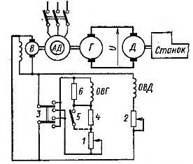
Rice. 1. System generator - DC motor (dpt)
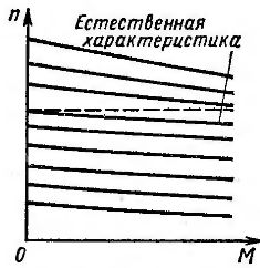
Rice. 2. Mechanical characteristics of the generator — DC motor system
They have a greater slope than the characteristics of the same electric motor fed from the constant network, since in the G — D system the voltage U at a constant excitation current of the generator decreases with increasing load according to the dependence:
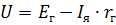
where e.g. and rg — e, respectively. etc. pp. and the internal resistance of the generator.
By analogy with asynchronous motors, we denote
This value characterizes the decrease in engine speed when the load increases from zero to nominal. For parallel mechanical characteristics
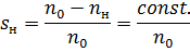
This value increases as n0 decreases. At large values of sn, the specified cutting conditions will change significantly with random load fluctuations. Therefore, the voltage regulation range is usually less than 5:1.
As the rated power of the motors decreases, the voltage drop across the motors increases and the mechanical characteristics become steeper. For this reason, the voltage regulation range of the G -D system is reduced as the power decreases (for powers less than 1 kW to 3:1 or 2:1).
As the generator's magnetic flux decreases, the demagnetizing effect of its armature reaction affects its voltage to a greater extent. Therefore, the characteristics associated with low engine speeds actually have a greater slope than the mechanical characteristics.
The expansion of the control range is achieved by reducing the magnetic flux of the motor D by means of rheostat 2 (see Fig. 1), produced at the full flow of the generator. This method of speed regulation corresponds to characteristics located above the natural one (see Fig. 2).
The total control range, equal to the product of the control ranges of both methods, reaches (10 — 15): 1. Voltage regulation is constant torque control (since the magnetic flux of the motor remains unchanged). Regulation by changing the magnetic flux of the motor D is a constant power regulation.
Before starting the motor, D rheostat 2 (see Fig. 1) is completely removed and the motor flux reaches the highest value. Then the rheostat 1 increases the excitation of the generator G. This causes the voltage to increase and the speed of the motor D to increase. If the coil OVG is connected immediately to the full voltage UB of the exciter B, the current in it, as in any circuit with inductance and active resistance, will increase:
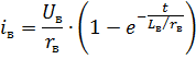
where rv is the resistance of the excitation coil, LB is its inductance (neglect the effect of the saturation of the magnetic circuit).
In fig. 3, a (curve 1) shows a graph of the dependence of the excitation current on time. The excitation current increases gradually; the rate of increase is determined by the ratio

where Tv is the electromagnetic time constant of the generator excitation winding; it has the dimension of time.
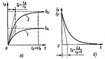
Rice. 3. Changing the excitation current in the G-D system
The change in generator voltage at start-up has approximately the same character as the change in excitation current. This enables the motor to automatically start with rheostat 1 removed (see Fig. 1).
The increase in the excitation current of the generator is often accelerated (forced) by applying at the initial moment to the excitation winding a voltage exceeding the nominal. Then the process of increasing the excitation will continue along curve 2 (see Fig. 3, a). When the current in the coil reaches Iv1, equal to the steady-state excitation current at the rated voltage, the voltage of the excitation coil is reduced to the nominal. The rise time of the excitation current to the nominal is reduced.
To force the excitation of the generator, the exciter voltage V (see Fig. 1) is selected 2-3 times higher than the nominal voltage of the generator excitation coil and an additional resistor 4 is introduced into the circuit. …
The generator-motor system enables regenerative braking. To stop, it is necessary for the current in the armature to change its direction. The torque will also change sign and instead of driving, it will become braking. Stopping occurs when the magnetic flux of the motor rheostat 2 increases or when the generator voltage decreases with rheostat 1. In both cases, e.g. etc. c. E of the motor becomes higher than the voltage U of the generator.In this case, motor D operates in generator mode and is driven into rotation by the kinetic energy of the moving masses, and generator G operates in motor mode, rotating the IM machine at supersynchronous speed, which at the same time switches to generator mode and supplies power to the network .
Regenerative braking can be done without affecting rheostats 1 and 2. You can simply open the generator excitation circuit (e.g. switch 3). In this case, the current in a closed circuit consisting of the excitation winding of the generator and resistor 6 will gradually decrease
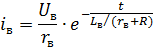
where R is the resistance of resistor 6.
The graph corresponding to this equation is shown in Fig. 3, b. A gradual decrease in the excitation current of the generator in this case is equivalent to an increase in the resistance of rheostat 1 (see Fig. 1) and causes regenerative braking. In this circuit, the resistor 6 connected in parallel with the excitation winding of the generator is a discharge resistor. It protects the excitation winding insulation from damage in the event of a sudden emergency interruption of the excitation circuit.
When the excitation circuit is interrupted, the magnetic flux of the machine decreases sharply, induces e in the turns of the excitation coil. etc. c. the self-inductance is so great that it can cause the winding insulation to break down. The discharge resistor 6 creates a circuit in which e. etc. c. the self-induction of the field coil induces a current that slows the decrease of the magnetic flux.
The voltage drop across the discharge resistor is equal to the voltage across the field coil.The lower the value of the discharge resistance, the lower the voltage of the excitation coil when the circuit is broken. At the same time, with a decrease in the resistance value of the discharge resistor, the current continuously flowing through it in normal mode and the losses in it increase. Both provisions must be considered when selecting the discharge resistance value.
After the excitation winding of the generator is turned off, a small voltage remains at its terminals due to residual magnetism. This can cause the motor to spin slowly at what is known as creep speed. To eliminate this phenomenon, the excitation winding of the generator, after being disconnected from the exciter, is connected to the terminals of the generator so that the voltage from the residual magnetism causes a demagnetizing current in the excitation winding of the generator.
To reverse the electric motor D, the direction of the current in the excitation coil of the generator OVG G is changed using switch 3 (or another similar device). Due to the significant inductance of the coil, the excitation current gradually decreases, changes direction and then gradually increases.
The processes of starting, stopping and reversing the motor in the considered system are highly economical, since they are carried out without the use of rheostats included in the armature. The motor is started and decelerated using light and compact equipment that controls only small field currents. Therefore, this "generator - DC motor" system is recommended to be used for work with frequent starts, brakes and reversals.
The main disadvantages of the motor-generator-DC system are relatively low efficiency, high cost and cumbersome due to the presence of a large number of electric machines in the system. The price of the system exceeds the price of an asynchronous squirrel-cage motor with the same power 8 — 10 times. Moreover, such electric drive system requires a lot of space.