Device and principle of operation of the VMPE-10 circuit breaker
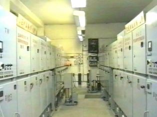
 VMPE series low-oil circuit breakers are widely used in 6-10 kV complete and enclosed switchgear. These switches have different designs depending on their purpose. The first versions of the VMP-10K type were intended for the KRU. The drive is supplied separately. Later, switches with a built-in spring or electromagnetic drive of the VMPP and VMPE types appeared. The series of these switches are designed for rated currents up to 2300 A and breaking currents up to 31.5 kA.
Circuit breakers are maximally unified and differ from each other in their rated current, wire cross-section and terminal dimensions, as well as in terms of rated breaking current in the design of the breaker chambers and racks. There are also slight design differences depending on where the breaker is released.
The switch type is conventionally designated as follows, for example, VMPE-10-1000-20U2, where V — circuit breaker, M — low-oil, P — pole-hung version, E — electromagnetic drive, 10 — rated voltage, kV, 1000 — rated current, A, 20 — rated breaking current, kA, U2 — climate version and category available …
The air temperature of the ambient switchgear for regions with a temperate climate is from minus 25 ° C to + 40 ° C. The relative humidity should not exceed 80% at a temperature of 20 ОБ. The environment must be explosion-proof, not contain aggressive gases and vapors in a concentration that destroys metals and insulation, not be saturated with conductive dust and water vapor.
Consider the device and principle of operation of the main parts of the VMPE-10 circuit breaker with a rated breaking current of 20 — 31.5 kA. The main technical parameters of the circuit breaker:
-
Nominal voltage — 10kV
-
Rated currents — 630, 1000 and 1600 A.
-
Rated breaking current 20 and 31.5 kA
-
Switching resource, the number of total on and off operations - 10 and 8, respectively.
-
Mechanical life — 2000 cycles.
-
The weight of the breaker without oil is 200 kg.
-
Oil weight — 5.5 kg.
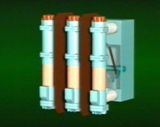
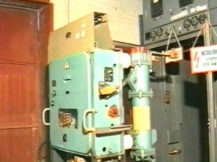
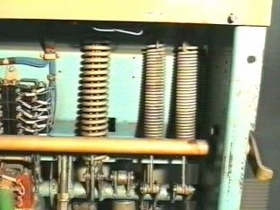
The circuit breaker consists of a frame which is a base and three poles attached to it on insulators. Insulation barriers are installed between the poles. The circuit breaker frame contains a DC electromagnetic drive, a main shaft with levers and a kinematic linkage, and an insulating rod connecting the circuit breaker and drive shafts. Opening springs and buffer devices are also installed inside the frame.
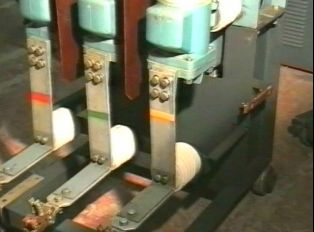
The breaker pole consists of a moisture-proof insulating cylinder with metal flanges, a housing to which the pole head is attached.At the top, the pole is closed by a cover made of insulating material with a ball valve. The pole is also covered with a cover underneath. Inside the pole housing is a mechanism for moving the movable contact, consisting of two levers firmly attached to a common shaft. The outer lever is connected by an insulating rod to the switch shaft, which is connected to the drive shaft by a system of levers. The inner arm is hinged with two movable contact shackles.
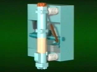
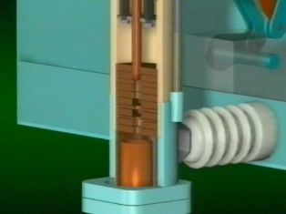
Two guide rods are attached to the pole head. Between them and the moving contact, wires (roller current collectors) are installed downwards. A fixed contact with a socket and an oil drain bolt are mounted on the bottom cover. An arc chute consists of a pack of insulating plates. The shape of the plates and the order in which they are arranged form blow channels and oil pockets that determine the direction of blow to extinguish the arc.
The arc extinguishing chamber in circuit breakers with a breaking current of 20 kA from transverse oil burst, in circuit breakers with a breaking current of 31.5 kA - from anti-transverse oil burst. Each pillar is equipped with an oil level indicator.
When the contacts of the switch diverge, an arc occurs between them, which vaporizes and decomposes the oil, forming a large amount of gas-oil mixture around it. The flow of gas-oil mixture, receiving a certain direction in the arc extinguishing device, extinguishes the arc.
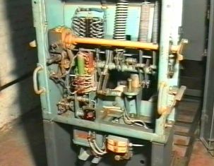
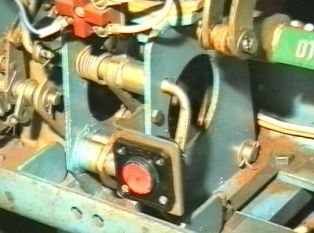
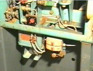
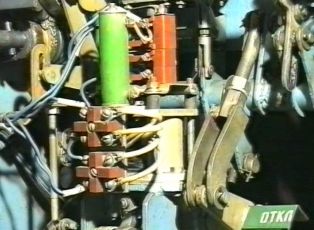
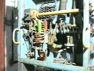
Drive of the VMPE-10 circuit breaker consists of a mechanism and two electromagnets — on and off. The closing electromagnet is designed to provide dynamic closing of the circuit breaker and consists of a movable rod core, spring, coil and magnetic circuit.At the bottom of the base, there are rubber seals installed that act as a buffer for the core to fall after the activation process is complete. The main bracket has marks and tabs for installing the manual release lever. The trip solenoid is designed to open the circuit breaker when commanded by the control switch or protection relay.
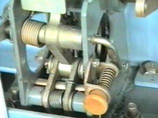
The actuator is a flat lever system and is designed to transfer movement from the closing solenoid rod to the switch mechanism and provide free tripping. The quick closing of the breaker occurs due to the energy of the closing solenoid of the drive and the tripping due to the energy of the opening springs of the breaker itself.
Consider the operation of the VMPE-10 switch when it is turned on. The switch turns on when power is applied to the switched solenoid coil. In this case, the electromagnetic core drawn into the coil acts with the rod on the pulley of the lifting mechanism and then through the clamp of the lever of the driving output shaft. The other bracket rests with its roller on the disconnecting stick, which ensures the immobility of the axis of the disconnecting mechanism roller during the closing of the circuit breaker. The detent pawl, under the action of the contoured detent mechanism, retracts to the left and sinks behind this axis at the end of engagement, detaining the actuator in the actuated position.
The rotation of the drive output shaft is transmitted through the system of levers to the breaker shaft and then through the insulating rods and straightening mechanisms to the movable contacts of the breaker. The switch closes.At the same time, the circuit breaker opening springs are stretched simultaneously.
Consider the operation of the VMPE-10 circuit breaker when it is turned off. The breaker is tripped by the opening springs when voltage is applied to the opening solenoid coils or when the manual control button is pressed. In this case, pulling the release solenoid core or button releases the release rod from engagement with the roller. The lever of the output shaft of the drive begins to rotate counterclockwise, the axis of the roller of the power mechanism is lowered by the retaining stick. At the beginning of the rotation of the drive shaft, the supply circuit of the closing electromagnet opens and its core returns to its original position. The device is then ready to power on again.
Under the action of the opening springs, the movable contacts of the circuit breaker are actuated by the straightening mechanisms. The switch is off.
The free tripping mechanism of the drive enables the circuit breaker to be opened not only from the fully closed position, as in the above case, but also from the unclosed position.
We examined the design and operation of the main parts of the VMPE-10 circuit breaker during various operations. We hope this article will help you to read the switch instructions.