Diagram and principle of operation of the transformer load switch
 In transformers and autotransformers with on-load voltage regulation (OLTC), an applied circuit and contact system that allows you to switch the number of winding turns without interrupting the electrical circuit.
Voltage regulation in on-load transformers is carried out on the high voltage side within ± 10% of the nominal voltage in eight steps of 2.5%, i.e. in the range ± 4×2.5%.
With a load switch, the transition from one winding branch to another without interruption of the current in the supply network is possible due to the use of a system of two parallel switching branches (P1 and P2) closed at current limiting reactor P, the midpoint of which is included in the transformer winding. The reactor is a three-phase inductive coil with a steel core with gaps. It is installed inside the transformer tank on the upper or lower bracket of the yoke.
In fig.1 shows a schematic diagram of a built-in load switch for 35 kV high voltage windings for one phase of a transformer. The circuit for 110 kV windings differs in that the control coils are not in the middle of the winding, but in the neutral, and a star is formed by connecting the midpoints of the three-phase reactors.
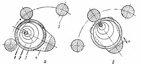
Rice. 1. Ring contact: a — working position, b — intermediate position, 1 — sliding ring, 2 — spiral band spring, 3 — spring axis, 4 — crankshaft, 5 — contact rod
It should be noted that the built-in load voltage regulation in autotransformers is done in the middle part of the windings, not on the neutral side.
In fig. 2 shows the sequence of switching from one branch to another (from contact A6 to contact A7) without interruption of the supply network.
Transformer Load Switch Operation
First, contactor K2 opens, then the vented branch is transferred through switch P2 to contact A7. Contactor K2 then closes again, as a result of which the switching section, through contacts A6 and A7, now closes on itself. Reactor P serves to limit the current in this section. Then the contactor K1 of the upper parallel branch opens and the switched-off switch P1 is also transferred to contact A7. Contactor K1 then turns on and the single-stage switching process is completed.
Three double switches P1 — P6 are placed inside the transformer tank as they operate without current. Contactors K1 — K6 are housed in a separate oil tank mounted on the side wall of the transformer tank. Each group of three switches and contactors is driven simultaneously by a common shaft.Switching takes place simultaneously in three phases.
The correct sequence of operation of the contactor and switches is achieved by proper adjustment of the cam washer.
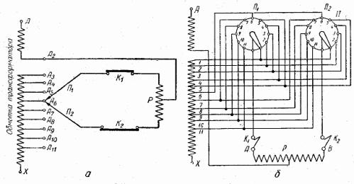
Rice. 2. Schematic and operation of the on-load control (OLTC): a — schematic diagram, b — connection diagram, P1, P2 — switches, K1, K2 — contactors, P — reactors, A — A11 — branches of regulating coils
On-load switching devices are equipped with an actuator that is driven by DC or AC motors.
The switching of the stages of the on-load tap changer is carried out remotely from the control panel and can also be carried out automatically under the action of a voltage relay. In addition, there is the possibility of manual control using a lever in the event of a malfunction of the motor drive or lack of power supply.
When the switching device is controlled by a motor drive, one complete transition to an adjacent stage takes about 3 seconds.