Selection of protective settings for 600 V lines at traction substations
 The setting current of line switches depends on the calculated load current of the line as well as the value of the short-circuit current at the end of the line.
Currently, in connection with the introduction of energy-intensive rolling stock and an increase in the frequency of movement, the setting current of the linear switches, depending on the calculated load current, is selected as follows:
1. for a tram
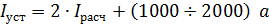
where Iras is the rated load current, 1000 is a constant value for single G-cars, 2000 is the same for 2-car G-cars,
2. for a trolleybus
The tripping current of the switches VAB-20, VAB-20M and VAB-36 from the magnetic system is chosen to be in the order of 4500-5000 amperes.
In practice, there are many lines in which the setting selected according to the rated load current exceeds the short-circuit current at the end of the line, which can lead to an unbroken short circuit and annealing of the contact wire.In this regard, reducing the setting current of the switches causes a lot of false tripping of the switches from normal load currents, which has a bad effect on the switches, accelerating their wear and increasing the number of repairs, deteriorating the quality of the supply line and increasing energy losses from the forced start of the rolling stock.
In order to be able to increase the settings of the switches and at the same time ensure that they trip short-circuit currents lower than the setting current, several types of line short-circuit protection have been developed. At the moment of traction substations the simplest current-time protection of 600 power lines in the TVZ received wide distribution.
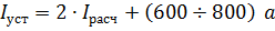
In fig. 1 shows a diagram of protection by current time. A shunt located in the circuit of the protected line is connected relay RT-40… When a current equal to or greater than the relay setting current flows in the line, the T contact closes the time relay circuit, which, with a predetermined time delay, closes its contact in the circuit breaker tripping circuit. If the line load drops before the time relay closes the trip circuit, the open contact of the current relay T will trip the time relay and the breaker will not open.
Rice. 1. Scheme of current protection of 600 V power lines
Time relay. VL-17 can be turned on in two ways:
• with preliminary supply of supply voltage (fig. 1, a)
• with applied supply voltage when the control contact is closed (fig. 1, b).
In fig. 2 shows a functional diagram of the VL-17 relay. The relay works as follows.When switching on according to the scheme with pre-supply, voltage is applied to terminals 1 and 3, and the circuit of relay P1 is open. The opening contact P1 keeps the capacitor C in the discharged state and the triode Tr in position 0. In this case, the output relay P2 is disabled.
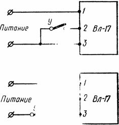
Rice. 2. Circuits for turning on the VL-17 relay: a — with preliminary supply of supply voltage, b — with supply of supply voltage when the control contact U is closed
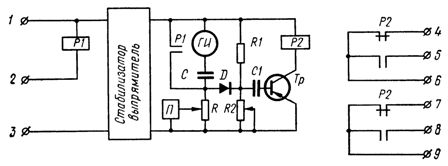
Fig. 3. Functional diagram of the VL-17 relay.
When contact y closes (see Fig. 2), relay P1 is activated, contact P1 opens and capacitor C begins to charge. The capacitor is charged through an adjustable resistor R, whose resistance value determines the delay time of the relay.
The value of the resistance of the resistor R is set by the switches P. When the voltage in the capacitor C reaches a certain value, the diode D will open, and from the generator GI through the capacitor C, the diode D, the capacitor C1 will pass a current pulse to the triode Tr, which will pass in position 1 and will turn on output relay P2, whose contacts are closed in the operating circuit.
When the contact opens on relay P1, the current stops, the contact P1 closes and the time relay will return to its original position. The opening voltage of diode D is set at the factory using an adjustable resistor R2.
When the time relay is turned on according to the circuit with a voltage supply, when the control contact is closed, the transition of the triode to the O position occurs when the voltage is applied to the relay circuit.
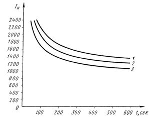
Rice. 4.Curves of thermal stability of the contact wire (the curves are taken at I = 800 A — long-term loading of two wires with a cross section S = 85 mm2 and the maximum heating temperature of the wire 100 ° C) 1 — toc ° = 5 ° C, 2 — toc ° = 20 ° C, 3 — toc ° = 40 ° C
The VL-17 time relays are manufactured for voltages of 127 or 220 V and for a range of time delays ranging from 0.1 to 200 sec.
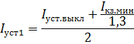
To create a time delay, you can use other types of time relays that fit the range of time delays. The setting of the current protection relay at the current time is determined by the expression:
where Isc.min is the minimum short-circuit current of the line, 1.3 is the reliability factor.
The time delay of the overcurrent protection is determined by the heating curve of the contact wire depending on the breaker setting current (Fig. 4).
The advantages of the described protection are ease of installation and operation and low cost.
The main disadvantage of this protection is that its time delay is independent, that is, it does not change depending on the temperature change of the contact wire and the magnitude of the load current. Therefore, there are cases of false triggering of the protection. This can be avoided by increasing the protection response time, which can lead to annealing of the contact wire. Therefore, on some lines it is necessary to install several sets of protection: one with a longer time delay at lower operating current, the other with a shorter time delay at higher operating current.
When installing two TVZ sets, the current and time settings are selected as follows:
• the current setting of the first set is selected by the expression
and the time setting of the first set is along the heating curve of the contact probe, depending on the current of the switch setting,
• the current setting of the second TVZ set is selected by the expression
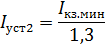
the time setting of the second set is taken from the heating curve of the contact wire, depending on the setting current of the first set.
Since the PT-40 winding is connected directly to the shunt and has a potential of 600 V, the insulation between the winding and the contacts, between the winding and the frame (ground) is tested with a voltage of 5 kV at industrial frequency. The resistance of the connecting wires from the shunt to the PT-40 relay must be minimal.
Employees of Mosgortransproekt have developed a device for an integrator of current protection — ITVZ. In this protection, instead of a relay, a coil of a magnetic amplifier is connected to the shunt. The output coil of the magnetic amplifier is connected to the timing relay VL-17.
The advantage of this protection is that it has a dependent characteristic, that is, the response time depends on the magnitude of the current flowing in the power circuit. This protection indirectly, through the current in the protected circuit, monitors the heating temperature of the contact wire.
The protection is adjusted in such a way that the shape of the dependence curve is similar to the shape of the heating curve of the contact wire and in the same ordinates it would be below the heating curve.
The disadvantages of this protection are the relatively high cost and complexity, both in installation and in commissioning and operation, compared to TVZ.
The Utility Academy has developed a thermal protection for 600 V lines, which is currently undergoing operational testing.This protection consists of a piece of contact wire connected in series to the substation with the supply line circuit. A hole is made in the wire, into which a thermistor is inserted, which has a relay effect. At a certain temperature, the resistance of the thermistor drops sharply and at the same time a relay is triggered, acting to open the switch. When the wire cools to a certain temperature, the thermistor recovers its resistance and the relay disappears.
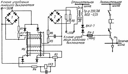
Rice. 5. Schematic diagram of the IKZ short-circuit tester
In addition to protecting the lines from low short-circuit currents, in order to reduce the wear of the switches and increase the reliability of the power supply of the lines, it is necessary to exclude the possibility of turning on the line switch if the short circuit has not disappeared in the line . For this purpose, a special line testing device developed by Moogortransproekt is used - short circuit finder (discriminator) IKZ.
When the line switch is turned off, its auxiliary contact closes the circuit of the primary winding of the transformer TP — p (Fig. 5) and from its secondary winding, through the valves ON, a half-wave current test current is sent to the line. In addition, the supply circuit of rectifier bridge 1 (I-36 V) is closed.
The value of the test current sent by the IKZ device to the line depends on the value of the line resistance.The short-circuit detector is adjusted in such a way that when the line resistance exceeds 1 — 1.2 ohms, the IKZ relay gives permission to automatically turn on the line switch, and if the line resistance is less than 0.8-0 .6 ohms, The IKZ relay breaks the auto-close switch.
The voltage drop across the resistors P7 and P8, in parallel with which the rectifier bridge 2 is connected, depends on the magnitude of the test current. The interaction of the magnetic fluxes in the magnetic amplifier MU, created by the amplifier coils connected to the rectifier bridges 1 and 2, determines the operation of the IKZ relay.