Control methods in automation systems
V automation systems Three methods of control are applied:
1) by deviation of the controlled value,
2) by disturbance (by load),
3) combined.
Method of regulation by deviation of the controlled variable Let us consider using the example of a DC motor speed control system (Fig. 1).
During operation, the motor D, as the object of regulation, experiences various disturbances (changes in the load on the motor shaft, the voltage of the supply network, the speed of the motor driving the armature of the generator D, changes in the ambient temperature, which in turn lead to change in the resistance of the windings, and hence the currents, etc.).
All these perturbations will cause the engine speed D to deviate, which will cause a change in e. etc. v. tachogenerator TG. Rheostat P is included in the circuit of the tachogenerator TG1... Voltage U0 taken by the rheostat P1 is included against the voltage of the TG tachogenerator. This results in a voltage difference e = U0 — Utg which is fed through the amplifier Y to the motor DP which moves the slider of the rheostat P.Voltage U0 corresponds to the set value of the controlled variable — rotation frequency ωО, and the tachogenerator voltage Utg — the current value of rotation speed.
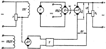
Rice. 1. Schematic diagrams for closed-loop DC motor speed control: R — rheostat, OVG — generator excitation coil, G — generator, OVD — motor excitation coil, D — motor, TG — tachogenerator, DP — rheostat slide drive motor, U — amplifier.
If, under the influence of disturbances, the difference between these values (deviation) exceeds a predetermined limit, then the regulator will receive a reference action in the form of a change in the excitation current of the generator, which will cause this deviation to decrease. A general deflection system is represented by the diagram in fig. 2, a.
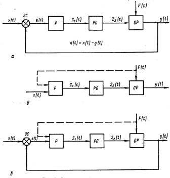
Rice. 2... Schemes of regulation methods: a — by deviation, b — by disturbance, c — combined, P — regulator, RO — regulatory body, OR — object of regulation, ES — element of comparison, x(T) is the setting, Z1 (t) and Z2 (t) — internal regulatory influences, (T) — adjustable value, F(T) is a disturbing effect.
Deviation of the controlled variable activates the regulator, this action is always directed in such a way as to reduce the deviation. To obtain the difference in values ε(t) = x(t) — y (f), a comparison element ES is introduced into the system.
The action of the regulator in the control of deviations occurs regardless of the reason for the change in the controlled variable. This is undoubtedly the great advantage of this method.
A method of disturbance control, or disturbance compensation, is based on the fact that the system uses devices that compensate for the influence of changes in the disturbance effect.
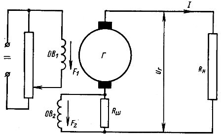
Rice. 3... Schematic diagram of DC generator voltage regulation: G — generator, ОВ1 and ОВ2 — excitation coils of the generator, Rн — load resistance, F1 and F.2 — magnetomotive forces of the excitation coils, Rsh — resistance.
As an example, consider the operation of a direct current generator (Fig. 3). The generator has two excitation windings: OB1 connected in parallel with the armature circuit and OB2 connected to a resistance Ri... The field windings are connected in such a way that their ppm. F1 and F.2 add. Generator terminal voltage will depend on total ppm. F = F1 + F2.
As the load current Az increases (the load resistance Rn decreases) the generator voltage UG should have decreased due to an increase in the voltage drop across the generator armature, but this will not happen because ppm. F2 excitation coil OB2 increases as it is proportional to the load current Az.
This will lead to an increase in the total ppm and, accordingly, to an equalization of the generator voltage. This compensates for the voltage drop when the load current changes — the main disturbance of the generator. Resistance RNS in this case it is a device that allows you to measure interference — load.
In the general case, a diagram of a system operating by the disturbance compensation method is shown in Fig. 2, b.
Anxious influences can be caused by a variety of reasons, so there may be more than one of them.This complicates the analysis of the operation of the automatic control system. It is usually limited to looking at disturbances caused by the root cause, such as load changes. In this case, the regulation is called load regulation.
A combined method of regulation (see Fig. 2, c) combines the two previous methods: by deviation and outrage. It is used in the construction of complex automation systems where high-quality regulation is required.
As follows from fig. 2, in each adjustment method, each automatic adjustment system consists of adjustable (adjustment object) and adjusting (regulator) parts. In all cases, the regulator must have a sensitive element that measures the deviation of the controlled variable from the prescribed value, as well as a regulating body that ensures the restoration of the set value of the controlled variable after its deviation.
If in the system the regulator receives the effect directly from the sensing element and is actuated by it, then such a control system is called a direct control system and the regulator is called a direct acting regulator.
In direct-acting regulators, the sensing element must develop sufficient power to change the position of the regulating body. This circumstance limits the field of application of direct regulation, since they tend to make the sensitive element small, which in turn creates difficulties in obtaining efforts sufficient to move the regulatory body.
Power amplifiers are used to increase the sensitivity of the measuring element and obtain enough power to move the regulating body. A regulator operating with a power amplifier is called an indirect regulator, and the system as a whole is called an indirect regulation system.
In indirect control systems, auxiliary mechanisms are used to move the regulatory body acting from an external energy source or due to the energy of the controlled object. In this case, the sensitive element acts only on the control element of the auxiliary mechanism.
Classification of automation control methods according to the type of control actions
The control signal is generated by the control system based on the reference variable and the signal from the sensor that measures the actual value of the controlled variable. The received control signal is fed to the regulator, which converts it into a control action of the drive.
The actuator forces the regulating body of the object to take such a position that the controlled value tends to the set value. During system operation, the current value of the controlled variable is continuously measured, therefore the control signal will also be generated continuously.
However, the regulating action of the drive, depending on the device of the regulator, can be continuous or intermittent. In fig. 4, a shows the deviation curve Δu of the controlled value y in time from the set value y0, while at the same time in the lower part of the figure it is shown how the control action Z must be changed continuously.It is linearly dependent on the control signal and coincides with it in phase.
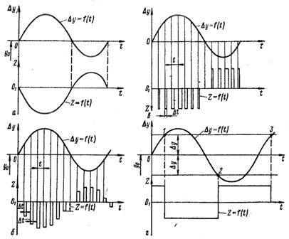
Rice. 4. Diagrams of the main types of regulatory influences: a — continuous, b, c — periodic, d — relay.
Regulators that produce such an effect are called continuous regulators, and the regulation itself is a continuous regulation... Regulators built on this principle work only when there is a control action, that is, until there is a deviation between the actual and the prescribed value of the controlled variable.
If during the operation of the automation system, the control action with a continuous control signal is interrupted at certain intervals or is supplied in the form of separate pulses, then the controllers operating on this principle are called periodic regulators (step or pulse)... In principle, there are two possible ways to form a periodic control action.
In fig. 4, b and c show the graphs of the intermittent control action with continuous deviation Δ from the controlled value.
In the first case, the control action is represented by separate pulses of the same duration Δt, following in equal time intervals T1 = t2 = t in this case the magnitude of the pulses Z = e(t) is proportional to the value of the control signal at the moment of formation of the control action.
In the second case, all pulses have the same value Z = e(t) and follow at regular intervals T1 = t2 = t, but have different durations ΔT. In this case, the duration of the pulses depends on the value of the control signal at the time of formation of the control action.The regulatory action from the regulator is transferred to the regulatory body with corresponding discontinuities, due to which the regulatory body also changes its position with discontinuities.
In practice, they are also widely used relay control systems... Let's consider the principle of operation of relay control, using the example of the operation of a regulator with two-position control (Fig. 4, d).
On-off control regulators include those regulators that have only two stable positions: one — when the deviation of the controlled value exceeds the set positive limit + Δy, and the other — when the deviation changes sign and reaches the negative limit -Δy.
The adjusting action in both positions is the same in absolute value but different in sign, and this action through the governor causes the governor to move sharply in such a way that the absolute value of the deflection always decreases. If the value of the deviation Δу reaches the permissible positive value + Δу (point 1), the relay will trigger and the control action -Z will act on the object through the regulator and the regulating body, which is opposite in sign but equal in magnitude to the positive value of the control action + Z. The deviation of the controlled value will decrease after a certain period of time.
Reaching point 2, the deviation Δy will become equal to the permissible negative value -Δy, the relay will work and the control action Z will change its sign to the opposite, etc. Relay controllers, compared to other controllers, are simple in design, relatively cheap and are widely used in those facilities where high sensitivity to disturbing influences is not required.