Capacitor braking of asynchronous motors
Capacitor braking of electric motors
Capacitor braking of low-power asynchronous motors and combined braking methods with its use have become widely used in recent years. In terms of braking speed, shortening the braking distance and improving accuracy, capacitor braking often gives better results than other methods of braking electric motors.
Capacitor braking is based on the use of the phenomenon of self-excitation of an induction machine or, more correctly, capacitive excitation of an induction machine, since the reactive energy required to excite the generator mode is supplied by capacitors connected to the stator winding. In this mode, the machine operates with a negative relative to the rotating magnetic field created by free currents excited in the stator winding, sliding, developing a braking torque on the shaft. Unlike dynamic and restorative, it does not require consumption of exciting energy from the network.
Capacitor braking circuits for electric motors
Capacitor braking of asynchronous motors
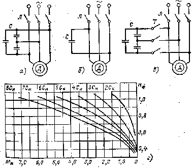
The figure shows the circuit for turning on the motor during capacitor shutdown. Capacitors are included in parallel with the stator winding, usually connected in a delta pattern.
When the engine is disconnected from the mains capacitor discharge currents I create magnetic fieldlow angular velocity rotation. The machine enters regenerative braking mode, the rotation speed is reduced to a value corresponding to the rotation speed of the excited field. During the discharge of the capacitors, a large braking torque occurs, which decreases as the rotation speed decreases.
At the start of braking, the kinetic energy stored by the rotor is quickly absorbed with a short braking distance. Stopping is sharp, impact moments reach 7 Mnom. The peak value of the braking current at the highest values of the capacity does not exceed the starting current.
As the capacity of the capacitors increases, the braking torque increases and the braking continues to a lower speed. Studies show that the optimal capacity value is in the range of 4-6 sleeps. The capacitor stop stops at a speed of 30 — 40% of the rated speed when the rotor speed becomes equal to the frequency of rotation of the stator field from the free currents arising in the stator. In this case, more than 3/4 of the kinetic energy stored by the drive is absorbed in the braking process.

For a complete stop of the motor according to the scheme of figure 1, a, it is necessary to have a moment of resistance of the shaft. The described scheme compares favorably with the absence of switching devices, ease of maintenance, reliability and efficiency.
When the capacitors are firmly connected in parallel with the motor, only those types of capacitors that are designed for continuous operation in the AC circuit may be used.
If the shutdown is carried out according to the diagram in Figure 1 with the connection of capacitors after disconnecting the motor from the network, it is possible to use cheaper and small-sized metal paper capacitors of types MBGP and MBGO, designed for operation in Schemes of constant and pulsating current, as well as dry polar electrolytic capacitors (CE, KEG, etc.).
Capacitor braking with capacitors loosely connected according to the delta circuit is recommended to be used for fast and accurate braking of electric drives, on the shaft of which a load torque of at least 25% of the rated torque of the motor acts.
A simplified scheme can also be used for capacitor braking: single-phase capacitor switching (Fig. 1.6). To obtain the same braking effect as with three-phase capacitor switching, it is necessary that the capacitance of the capacitor in a single-phase circuit is 2.1 times greater than the capacitance in each phase in the circuit of Fig. 1, a. In this case, however, the capacity in a single-phase circuit is only 70% of the total capacity of the capacitors when they are connected in three phases.
Energy losses in the motor during capacitor braking are the smallest compared to other types of braking, which is why they are recommended for electric drives with a large number of starts.
When choosing equipment, it should be borne in mind that the contactors in the stator circuit must be rated for the current flowing through the capacitors.In order to overcome the disadvantage of capacitor braking — the stopping of action until the motor stops completely — it is used in combination with dynamic magnetic braking.
Dynamic capacitor brake circuits

Circuits of capacitor-dynamic braking by magnetic braking.
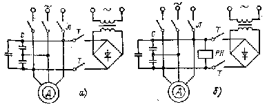
The two basic DCB circuits are shown in Figure 2.
In the circuit, direct current is supplied to the stator after stopping the capacitor braking. This chain is recommended for precise braking of the drive. The DC power supply must be performed as a function of the machine path. At reduced speed, the dynamic braking torque is significant, which ensures a quick final stop of the engine.
The effectiveness of this two-stage braking can be seen from the following example.
In the dynamic braking of the AL41-4 engine (1.7 kW, 1440 rpm) with the external moment of inertia of the shaft, which is 22% of the moment of inertia of the rotor, the braking time is 0.6 s, and the braking distance is 11 .5 revolutions of the shaft.
When capacitor braking and dynamic braking are combined, the braking time and distance are reduced to 0.16 s and 1.6 shaft revolutions (the capacitance of the capacitors is assumed to be 3.9 Sleep).
In the diagram of fig. 2b, the modes overlap with DC supply until the end of the capacitor shutdown process. The second stage is controlled by the PH voltage relay.
Capacitor-dynamic braking according to the diagram in fig. 2.6 allows to reduce the time and braking distance by 4 — 5 times compared to dynamic braking with a capacitor according to the scheme in fig. 1, a.The deviations of the time and the path from their average values in the sequential action of the capacitor and the modes of dynamic braking are 2 — 3 times less than in the circuit with overlapping modes.
