An overview of modern electrical products using the example of products from Moeller
The range of electrical products currently manufactured is so wide that a detailed description of its varieties, characteristics and characteristics of use would take a multi-volume publication. This is not necessary for the review. It is enough to show with the example of individual electrical appliances the possibilities opened up by the use of modern equipment.
Electrical engineering, which appeared simultaneously with the development of electricity, developed gradually — from the simplest connectors, disconnectors and protective devices to the most complex microprocessor systems that ensure the coordinated operation of hundreds of electrical devices without any human involvement — automatically.
The development of power supply and automation systems based on Moeller products (as well as ABB, Legrand, Schneider Electric, etc.), thanks to unification and standardization, currently consists in the selection of existing elements and devices and their layout in a specific a scheme that can be arbitrarily complex and multi-level — the range is wide enough for any engineering solutions. You just need to know exactly what the manufacturer offers the developer — and starting from that, continue to develop the details by including additional information (catalogs, sites, technical reviews, etc.).
The traditional division of products into industrial and household products is currently unjustified — the electrification of modern homes sometimes becomes a serious task, not inferior in complexity to the design of an industrial assembly line. Multi-level protection, automation of irrigation and heating systems, remote control — this is an incomplete list of systems used for household needs. Based on this, it would be advisable to look at electrical products as a whole, — in this way we avoid unnecessary repetitions and get a more or less clear picture.
Display and control system
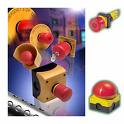 In the event that the complexity of the electrical system makes it difficult to manage devices scattered over the territory, or constant monitoring of their condition is required, an indicator and control unit is assembled, combining control elements (buttons, switches, joysticks) and display elements (bulbs and boards).This allows, without moving from one place, to manage, for example, an assembly line, while exercising control over the health of all its elements and the assembly process.
Moeller's assortment policy is such that the control elements have a modular design: each of them consists of at least three elements: the outer part protected from water and dust, the middle connecting part and the lower contact part.
The outer part can be: a transparent lens (for light bulbs), a button (transparent and not), a handle (for rotary switches and joysticks), a lock cylinder (for key switches) or a potentiometer equipped with a scale. The middle part is the same for all elements - on one side the outer element is inserted into it, and on the other, the inner ones snap into place - up to four pieces. The lower parts are individually selected from two types of elements: contacts (for closing and opening) and LED modules (for light bulbs and buttons).
The already assembled controls can be mounted in branded boxes (from 1 to 12 standard places), on a dinrack (using a special adapter) or in any suitable case with a 22 mm hole (for RMQ-Titan). Buttons and lamps are equipped with various symbolic overlays or information plates informing about the purpose of this or that control element.
For more complex control systems, it may be advisable to use elements of the RMQ-16 series, which differ in the rectangular shape of the external elements, which allows them to be mounted more compactly - end-to-end, and smaller platform diameter — 16 mm.
If it is necessary to monitor the state of the generator installation not from the control panel, but, say, from two or three points distant from the device, you can use special signal towers, which are assembled from multi-colored cylinders with constant light, flashing and blinking (strobe lights). In addition, the tower may include an audible indicator (buzzer) that usually signals an emergency.
Sensors for automation systems
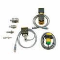 The operation of any automatic system (from blinds to the assembly line) is primarily based on the principle of feedback: the control system monitors the position of the moving parts of the mechanism and, in accordance with this position, regulates the operation of the engine (hydraulic) drives, which ultimately account allows achieving a well-coordinated operation of the entire system. The "eyes and ears" of the automatic system are sensors whose contacts are switched at the moment of a certain change in the external environment. Depending on what exactly the sensor responds to, it refers to one or another group of sensors.
The simplest and most common sensors — limit switches (LS and AT series) — are actuated by mechanical action on their pin, which is aligned with the contact group inside their housing. The base module of such a sensor, depending on the requirements imposed on it, is equipped with various attachments: a roller and a pin, the assortment of which, like the internal structure of the base module, is very diverse and is selected individually.
If you want to capture the movement of a metal object, the so-called capacitive (LSC series) or inductive (LSI series) sensor. The pressure sensitive sensor (which is set from 0.6 bar and above) is available in the MCS series.
Multi-function relays
 Various sensors that respond to changes in the environment are described above. Now we will look at devices that process signals from sensors and directly control electrical units.
The simplest automation device — the shutter control mechanism — does not require any special control devices: the limit switch contacts directly control the drive motor. But what if there is not one sensor, but there are, for example, five of them, and the signals from them should cause not just the engine to turn on, but also the execution of part of a complex program, say, to control the heating and ventilation of the museum warehouse ?
In the middle of the 20th century, such a task would have caused a serious headache for the designer, since such tasks were performed by complex diode-relay circuits, which were problematic for installation and commissioning, not to mention possible repairs. But now, thanks to the advancements in science and technology that led to the emergence of microcontrollers, the task has become so simple that a student can handle it.
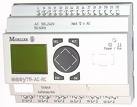
These are multifunctional relays from the Easy series. Such a relay is a small-sized unit, in the upper part of which there are input terminals (for sensors) and power terminals, and in the lower part there are output terminals, from which signals are sent to the controlled devices. Despite the external simplicity, such a device hides impressive capabilities — a single Easy 800 series relay can control a small assembly shop, and when several relays are combined with a network cable in a system, it is almost impossible to exhaust its capabilities.
Installing the Easy relay involves several steps.First, a control algorithm is developed that takes into account the needs of the customer and the characteristics of the work process: depending on the controlled processes, discrete sensors (limit switches, phase control relays, etc.) or analog (regulators) are selected.
Depending on the complexity of the resulting algorithm, a specific type of relay is selected (simple, 500 series or multifunctional — 800 series, with or without a display). Then, using a computer and a special cable, the selected relay is programmed — the specified algorithm is saved in the relay memory. After that, the relay is tested, installed and connected to the power supply (220 or 24V), as well as to the wires from the sensors and from the drives.
If necessary, the relay is equipped with a portable graphic display MFD-Titan (resistant to dust and moisture), which allows displaying information about controlled processes, both in the form of numbers and in the form of graphic diagrams, the view of which is also configurable using a computer.
Contactors
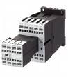
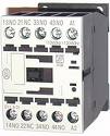 The relays described above, as well as the control devices, have one drawback: the maximum current they can pass is low — up to 10A. In most cases, the controlled devices (especially industrial ones) consume more current, therefore special transitional devices - contactors - are needed for their control. In these devices, the large current required to power a powerful device is controlled by a small current passing through the control coil. In this case, a large current flows through the individual high-current contacts.
The smallest contactors (DILA, DILER, DILR) are used when the control current is very small and the controlled one is not too high (no more than 6 A). At higher controlled current, two-stage control is used.These contactors are small in size and are placed on a standard DIN rail. They are equipped with auxiliary contacts, suppressors (spark arresters) and pneumatic delay relays (for DILR).
DILE (E) M contactors are similar to the previous ones, but have a higher operating current (6.6 — 9 A).
Next in level are the recently appeared contactors of the DILM series (7 — 65). They, like the previous ones, are mounted on a DIN rail, but are designed for a higher current — from 7 to 65 A. They are supplemented with front and side additions. contacts, suppressors, as well as thermal relays used when powering electric motors (see below).
 DIL contactors (00M — 4AM145) are large and board mountable. Of the medium power contactors (current from 22 to 188 A), they have the most complete set: side, rear and front additional. contacts, suppressor, thermal relay and pneumatic delay relay.
More powerful DILM contactors (185 — 1000) with power up to 1000 A, have larger dimensions, are installed on a mounting plate and are equipped with side additions. contacts, a mechanical interlock for collecting in a reversible circuit (see below), a thermal relay, a protective cap for a thermal relay, as well as clamps for cable clamps.
In addition to individual contactors, contactor assemblies are also produced for starting three-phase motors (star-delta — SDAIN series) and for automatic transfer switch (automatic backup input) — DIUL series.
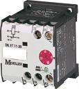
In addition to the remote control of the power load, the contactor can be used as a device for starting and protecting the electric motor — together with a thermal relay that contains a thermal release that opens the circuit in case of overload, a trip current regulator and a trip button , which opens the coil circuit and disable circuit. The reverse circuit is used when two contactors are operating in pairs and only one of them can be operating at any time — to supply backup power to the load in the event of a mains power failure.
Control relay
 Control relays are functionally independent devices that control the load depending on their function. Time delay relays contain a circuit that delays switching the load on or off for a predetermined period of time. Such a delay is necessary in systems that combine powerful inductive and powerful non-inductive loads (for example, electric motors and electric heaters) to prevent overloading the network at the time of switching on — the non-inductive load is switched on a little later when the motors enter a relatively low current operating mode. Also, these relays are used in automation devices.
The simplest delay relays of the DILET series have an electromechanical design and a delay time from 1.5 s to 60 h. Electronic time delay relays (ETRs) are smaller and allow delay times from 0.05 s to 100 h.
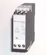
Voltage monitoring relays allow the load to shut down when the supply voltage changes critically, thus avoiding damage to the expensive and difficult-to-install main unit.
The EMR4-I relay monitors the single-phase voltage - its minimum and maximum limits, as well as, if necessary, the turn-on or turn-off delay.
The EMR4-F relay monitors the phase equality of the three-phase voltage and also protects the load from phase failure. The EMR4-A relay allows you to adjust the permissible unbalance of the monitored three-phase voltage.
 The EMR4-W relay is similar to the EMR4-I but is designed for three-phase voltage control. Liquid level control relays, as the name suggests, are used to maintain the level of a liquid (usually water) in a reservoir (such as a swimming pool).
The moment the liquid level exceeds the limits limited by the control contacts, the relay turns the pump on or off, supplying liquid to the tank. The series of these relays is called EMR4-N.
If for some reason the generator set housing is not grounded, it may be advisable to install an EMR4-R series relay that monitors the resistance between the unit housing and ground and shuts down the unit in the event that this resistance is dangerously exceeded. The resistance value at which the cutoff occurs is adjustable.
All relays of the EMR4 series are mounted on a DIN rail, have an indication of the current state of the device and allow a load of up to 5 A per line.
Switches for disconnectors
For manual tripping (power off) and switching of loads with a current consumption of up to 315 A, T (0-8) and P (1, 3 and 5) series power switches operated by a rotary handle are used.
They differ in the type of installation: open version (resistant to splashes and moisture), with panel mounting and with a false panel.In addition, the control handle can be equipped with a protective ring to prevent accidental actuation. The switch can be equipped with black and red handles of different sizes, as well as different mechanisms with individually selectable switching schemes (up to 16 switching directions).
The miniature switches of the TM series are similar to the previous ones, but smaller in size.
Start security devices
The operation of electric motors, wherever they are used, is characterized by the same requirements for their starting and operation - or rather, for the devices that provide them. This is how start-up protection devices appeared, which both smoothly start the electric motor and ensure its safe operation: control of the maximum load current, short circuit and the presence of the three phases.
Structurally, such a device is a single unit with an included handle and two regulators - the breaking current of the thermal release (from 0.6 to 1.5 nominal current) and the electromagnetic release current (up to 10 times the nominal one). These are PKZM series (from 0.1 to 65 A).
Starter protection devices PKZM01 are available for rated currents from 0.1 to 16 A and have small dimensions. They don't have a power button — it's replaced by START and STOP buttons in black and red. PKZM devices (0 and 4) have a rotary knob.
All PKZM devices, if necessary, are equipped with additional side and front contacts, remote handles with long axes (for installation in a cabinet), as well as surge protectors installed (like the starter protection devices themselves) on the din rail.
If the motor draws more than 63 A, then a NZM series power circuit breaker (see below) is used for protection.
Power switch disconnectors
 The protection of circuits under a large current load has a number of characteristics: the process of switching on and off is accompanied by a strong arc and sparks, and short circuit at high currents, it requires increased electrical strength from the safety switch — otherwise, instead of protection, it will burn itself. At currents above 400 A, the effort required to manipulate the machine becomes too great — this requires the introduction of a remote control mechanism.
The NZM series circuit breakers have sufficient electrical strength as well as an assortment of accessories to meet all modern safety requirements and equip the switchboard of a factory workshop or residential building.
A typical NZM machine (in basic configuration) is a rectangular plastic block with input and output contact pads and a shift lever at the front. At the bottom of the front are the current regulators of the thermal and electromagnetic releases, as well as the on and off delays, brought out under the slot. These machines are equipped with: cable clamps, side and front swivel handles, surge protection modules and motor drives that allow the machine to be turned on and off remotely. The same drives are used when installing automatic machines in the circuit of the automatic transfer switch (starting from 250 A, this circuit is assembled not on contactors, but on automatic machines).
In addition to the protective function, NZM (motor operated) circuit breakers are also used as disconnectors. Their arc cameras and power outlets make it easy and safe for people to disconnect a power line. Provide a safe power supply very powerful load (up to 6300 A), you can use serial machines of the IZM series. They have a built-in motor drive that allows you to control the machine by pressing a small button on the front. In addition, the IZM machine is equipped with a multifunctional relay with a display that shows both its status and the parameters of the power network. Modular automation.
Powerful machines, such as the NZM and IZM series machines, are used relatively rarely - such a powerful load is still rare. Much more often, when protecting a network, especially a household one, they use modular automation. Such devices are characterized by relatively low limiting currents (up to 125 A), standard (modular) housings of small dimensions and are mounted on a DIN rail.
Devices of this type are distinguished by their simplicity of installation, selection and operation. Their range is very wide — from simple circuit breakers to multifunctional automation devices. Standard sizes allow the installation of a wide variety of devices in unified plastic and metal boxes that differ only in the number of modules installed in them.
The X-pole series includes overcurrent, short circuit and leakage current circuit breakers.
Circuit breakers that protect the wiring connected to them from overloading and short-circuiting, which can lead to overheating and fire of the conductor, have a PL serial designation. PL4 circuit breakers have a breaking capacity standard for Russia and unacceptably low for Europe — 4.5 kA. Such machines are produced for rated currents from 6 to 63A.
The PL6 series includes machines with a European standard electrical strength of 6 kA and are currently the most widely used. They are produced for rated currents from 2 to 63A. If it is necessary to provide increased dielectric strength, PL7 (10 kA) machines are used. Their rated current varies from 0.16 to 63A.
In cases where the rated current exceeds 63A, but the machine must be of standard modular dimensions, you can use the device of the PLHT series — in addition to the standard values (20 — 63A, interruption 25 kA), they have currents of 80, 100 (20 kA) and 125A, with a breaking capacity of 15 kA.
Circuit breakers designed to protect a person from electric shock when accidentally touching a bare wire, as well as to prevent spontaneous combustion of a cable with old insulation, are produced in the PF series and are called RCDs (residual current devices).
The differences between the PF4, PF6 and PF7 series RCDs are similar to the differences between the PL4, PL6 and PL7 series of conventional circuit breakers (they differ in the ultimate breaking capacity). RCDs of the PFNM and PFDM series can withstand a maximum current of up to 125A, in addition, the PCDDM RCD has increased reliability and does not require monthly testing (like other devices). RCDs intended for the protection of people have rated leakage currents of 10 and 30 mA, for protection against spontaneous combustion — 100 and 300 mA. The latter, as a rule, are placed at the entrance — immediately after the typing machine.
Circuit breakers that structurally combine an RCD and a conventional machine are called differential circuit breakers and are produced in the PFL series. Like the previous modular devices, they have breaking capacities of 4.5 kA (PFL4), 6 kA (PFL6) and 10 kA (PFL7). All the above devices are equipped with additional contacts, remote releases, etc.
In addition to protective devices, a number of auxiliary devices are produced in a modular design that increase the convenience and safety of electricity consumption.
Circuit breakers of the IS and ZP-A series outwardly resemble automatic machines (PL), but do not have automatic release - they are used as main switches that disable the switchboard. Z-MS machines are similar to the PKZ devices described above, but are simpler and are designed to protect low-power electric motors (0.1-40 A).
 The Z-UR undervoltage relay, as its name suggests, switches off the connected load when the mains voltage falls below the limit set on this device.
The DS-G light-sensitive switches are activated when the lighting changes, which accompanies the change of time of day - for automatic on / off of the street lighting. They are available in three versions: with a sensor built into the relay, with a remote sensor and with a built-in timer.
Electromechanical timers Z-S and SU-G are designed to switch the load according to a given program every other day or week, and the minimum switching interval is 20 minutes (for daily timer) and 8 hours (for weekly).
The SU-O and Z-SDM timers are digital, with an LCD display showing the program and its progress.
The Z-ZR time relay provides a delay when turning on or off a load with a capacity of up to 2000 VA, the value of which is set from 50 ms to 30 minutes.
The Z-TL series relay performs the same function, but is simpler in design and is used to switch stair lamps. After applying a pulse from the power button to its input, it turns on the light for a time from 0.5 to 20 minutes, which can be set individually. To signal an emergency, a signal is needed to alert as many people as possible. The best from this point of view is a dial tone or ringtone. This is such a device, with the size of one standard module, which is produced in the Z-SUM / GLO series, on Rated voltage 230, 24 and 12V.
Nowadays, many doorbell manufacturers offer vintage style bell knobs, including metal ones. From electrical safety rules, the voltage passing through such buttons should not exceed 36V, therefore, in most calls, an additional 24V power circuit is provided. To be powered by a standard 220V network, a modular bell transformer of the TR-G series is used.
If the load on the network, when all loads are turned on at the same time, exceeds the maximum permissible, using the priority load relay of the Z-LAR series, you can ensure continuous operation of the most important user by quickly turning off all the others.