Classification of semiconductor rectifiers
A device designed to convert the energy of an alternating current source into direct current is called a rectifier. The rectifier can be represented in the form of a block diagram shown in fig. 1.
Let's characterize the main elements of the scheme:
a) a power transformer serves to match the input and output voltage of the rectifier and the electrical separation of the individual rectifier circuits (i.e. it separates the supply network and the load network);
b) a valve block provides a unidirectional flow of current in the load circuit, as a result of which the alternating voltage is converted into a pulsating voltage;
v) smoothing filter designed to reduce voltage ripples in the load to the required value;
G) Voltage regulator, used to stabilize the average value of the rectified voltage when the supply voltage fluctuates or when the load current changes.

Rice. 1 — Block diagram of the rectifier
The relationship between the parameters in the rectifier depends largely on the rectifier circuit.Under rectifier circuit understand the connection diagram of the transformer windings and the procedure for connecting the valves to the secondary windings of the transformer.
Rectifier circuits (rectifiers) are classified according to the following main characteristics:
1. By the number of phases of the alternating current supply, it distinguishes between single-phase rectifiers and three-phase rectifiers.
2. By the method of connecting valves to the secondary winding of the transformer — zero circuits using the zero (middle) point of the secondary winding of transformer and bridge circuits in which the zero point is isolated or the secondary windings of the transformer are delta connected.
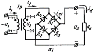
Single-phase bridge rectifier circuit
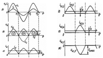
Timing diagrams of voltages and currents of a bridge rectifier
With a positive polarity of the voltage on the secondary winding of the transformer (polarity is indicated without brackets) in the interval 0 — υ1 (0 — π), the current is carried by diodes D1 and D2. The voltage drop across the diodes in the conduction interval is close to zero (ideal valves), therefore a positive half-wave of the voltage on the secondary winding of the transformer is applied to the load, creating a voltage ud = u2 on it. In the interval υ1 — υ2 (π — 2π) the polarity of the voltages u1 and u2 will be reversed, which will lead to the unlocking of diodes D3 and D4. In this case, the voltage u2 will be connected to the load with the same polarity as in the previous interval. Therefore, the output voltage ud with a purely resistive load of the bridge rectifier has the form of unipolar voltage half-waves (ud = u2).
3.Power consumption by load rectifiers are divided into low power (units of kW), medium power (tens of kW) and high power (Ppot> 100 kW).
4. Regardless of the power of the rectifier, all circuits are divided into single-cycle or half-cycle and two-cycle (full-wave).
Single-cycle — these are circuits in which the current passes through the secondary windings of the transformer once per period (half a period or part of it). All zero circuits are single.
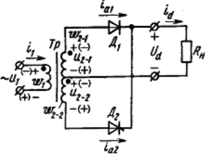 A single-phase full-wave rectifier circuit with the transformer zero-point output
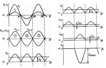
Timing diagrams of a single-phase zero-output rectifier with an active load
Full wave rectification in the circuit is achieved by making a transformer with two secondary windings. The windings are connected in series and have a common zero (center) point. The free ends of the secondary windings of the transformer are connected to the anodes of the valves D1 and D2, and the cathodes of the valves connected together form the positive pole of the rectifier. The negative pole of the rectifier is the common (neutral) connection point of the secondary windings. Thus, the transformer serves in this circuit both to match the magnitude of the supply voltage and the voltage in the load, and to create a middle (zero) point. It is obvious that the voltages at the terminals of the secondary windings of the transformer u1 and u2 (or EMF e1 and e2) are the same in magnitude and are shifted relative to the zero point by 180 °, i.e. are in antiphase.
 At any instant of time, this diode conducts a current whose anode potential is positive.Therefore, in the interval 0 — π, diode D1 is open and the phase voltage of the secondary winding of the transformer ud = u2-1 is applied to the load resistance Rn (Rd). Diode D2 in the range 0 — π is closed because a negative voltage is applied to it. At the end of the interval, the voltages and currents in the circuit are zero.
In the next operating interval of the π — 2π circuit, the voltages of the primary and secondary windings reverse their polarity, so that diode D2 will be open and diode D1 will be closed. Also, the processes in the correction chain are iterative. The rectified voltage curve ud consists of unipolar half-waves of the phase voltage of the secondary winding of the transformer. The shape of the load current with a purely resistive load follows the shape of the voltage. Diodes D1 and D2 conduct current in series for half a period.
5. By prior arrangement:
a) low-power rectifiers, as a rule, single-phase, used in control systems, to power individual blocks of electronic equipment, in measuring equipment, etc.;
b) medium and high power rectifiers serve as power sources for industrial installations.
6. Straightening schemes are divided into simple and complex. Simple circuits include single-phase and three-phase, neutral and bridge circuits. In complex (or complex circuits), several simple circuits are connected in series or parallel.
7. According to the type (nature) of the cargo. Single-phase rectifier circuits are characterized by significant pulsation of the rectified voltage. To reduce the voltage ripple on the load, smoothing filters are used based on the reactive elements of the chokes (L) and capacitors (C). The nature of the input circuit of the smoothing filter together with the load determines the type of load on the rectifier. A distinction is made between rectifier operation for active load (R — NG), active-inductive load (RL — NG), active load and capacitive filter (RC — NG).
Common to all rectifiers is their use mainly with RL — NG. This is due to the fact that low-power rectifiers most often work with an LC filter, and high-power rectifiers with an L filter.
7. By control, differentiate between uncontrolled and controlled rectifiers.
Ph.D. Kolyada L.I.
