What happens to the motor in case of phase loss and single phase operation
Under phase loss, we understand the single-phase mode of operation of the electric motor as a result of disconnection of the power supply of one of the conductors of the three-phase system.
The reasons for the loss of a phase from an electric motor can be: breaking one of the wires, burning one of the fuses; contact failure in one of the phases.
Depending on the circumstances under which the phase loss occurred, there may be different modes of operation of the electric motor and the consequences accompanying these modes. In this case, the following factors must be taken into account: the connection scheme of the windings of the electric motor ("star" or "delta"), the operating state of the motor at the moment of phase loss (phase loss can occur before or after switching on the engine, during load operation), the degree of engine loading and the mechanical characteristics of the working machine, the number of electric motors operating with phase loss and their mutual influence.
Here you should pay attention to the features of the mode under consideration. In three-phase mode, each phase of the winding flows with a current shifted in time by one-third of the period. When a phase is lost, both windings flow about the same current, there is no current in the third phase. Despite the fact that the ends of the windings are connected to two phase conductors of a three-phase system, the currents in the two windings coincide in time. This mode of operation is called single-phase.
The magnetic field generated by a single-phase current, unlike the rotating field generated by a three-phase system of currents, pulsates. It changes over time, but does not move around the circumference of the stator. Figure 1a shows the magnetic flux vector created in the motor in single-phase mode. This vector does not rotate, it only changes in magnitude and sign. The circular field is flattened to a straight line.
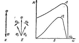
Picture 1. Characteristics of an induction motor in single-phase mode: a — graphical representation of a pulsating magnetic field; b — decomposition of the pulsating field into two rotating ones; c-mechanical characteristics of an induction motor in three-phase (1) and single-phase (2) operating mode.
Pulsating magnetic field can be considered as consisting of two fields of equal magnitude rotating towards each other (Fig. 1, b). Each field interacts with the rotor winding and generates a torque. Their combined action creates torque on the motor shaft.
In the event that a phase loss occurs before the motor is connected to the network, two magnetic fields act on a stationary rotor, which form two moments of opposite sign but equal in magnitude. Their sum will be zero.Therefore, when you start the motor in single-phase mode, it cannot reverse even if there is no load on the shaft.
If a phase loss occurs while the motor rotor is rotating, then a torque is generated on its shaft. This can be explained as follows. The rotating rotor interacts in various ways with the fields rotating towards each other. One of them, the rotation of which coincides with the rotation of the rotor, forms a positive (coinciding in direction) moment, the other - negative. Unlike the stationary rotor case, these moments will be different in magnitude. Their difference will be equal to the moment of the motor shaft.
Figure 1, c shows mechanical characteristics of the motor in single-phase and three-phase operation. At zero speed, the torque is zero; when it rotates in either direction, a torque occurs on the motor shaft.
If one of the phases is disconnected while the motor is running, when its speed was close to the rated value, the torque is often sufficient to continue operation with a slight reduction in speed. In contrast to the three-phase symmetrical mode, a characteristic hum appears. For the rest, there are no external manifestations of the emergency mode. A person who has no experience with asynchronous motors may not notice a change in the nature of operation of an electric motor.
The transition of an electric motor to a single-phase mode is accompanied by a redistribution of currents and voltages between the phases. If the motor windings are connected according to the "star" scheme, after the phase loss, a circuit is formed, shown in figure 2. Two series-connected motor windings are connected to the line voltage Uab, then the motor is in single-phase operation.
Let's do a little calculation, determine the currents flowing through the motor windings and compare them to the currents with a three-phase supply.
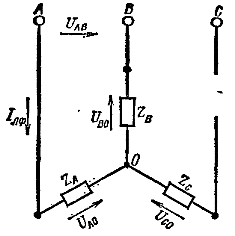
Figure 2. Star connection of motor windings after phase loss
Since the resistances Za and Zb are connected in series, the voltages of phases A and B will be equal to half of the linear one:

The approximate value of the current can be determined based on the following considerations.
Inrush current of phase A at phase loss

Starting current of phase A in three-phase mode

where Uao — phase voltage of the network.
Inrush current ratio:

From the ratio, it follows that in case of phase loss the starting current is 86% of the starting current in three-phase supply. If we take into account that the starting current of the squirrel-cage induction motor is 6-7 times higher than the nominal one, it turns out that a current flows through the motor windings Iif = 0.86 x 6 = 5.16 Azn, that is, more than five times the nominal. In a short period of time, such a current will overheat the coil.
From the above calculation, it can be seen that the considered mode of operation is very dangerous for the motor, and if it occurs, the protection must be turned off in a short time.
Phase loss can also occur after the motor is turned on, when its rotor will have a rotation speed corresponding to the operating mode. Consider the currents and voltages of the windings in the case of a transition to single-phase mode with a rotating rotor.
The value of Za depends on the speed of rotation. At start-up, when the rotor speed is zero, it is the same for both three-phase and single-phase modes. In operating mode, depending on the load and the mechanical characteristics of the engine, the speed of rotation may be different.Therefore, a different approach is needed to analyze current loads.
We will assume that the motor runs in both three-phase and single-phase mode. same power. Regardless of the connection scheme of the electric motor, the working machine requires the same power that is needed to carry out the technological process.
Assuming that the motor shaft power is the same for both modes, we will have:
in three-phase mode

in single-phase mode

where Uа — phase voltage of the network; Uаo — voltage of phase A in single-phase mode, cos φ3 and cos φ1-power coefficients for three-phase and single-phase modes, respectively.
Experiments with an induction motor show that in fact the current almost doubles. With some margin it is possible to consider I1a / I2a = 2.
To assess the degree of danger of single-phase operation, you must also know the load on the motor.
As a first approximation, we will consider the electric motor current in three-phase mode proportional to its load on the shaft. This assumption is valid for loads above 50% of the rated value. Then you can write Azf = Ks NS Azn, where Ks — load factor of the motor, Azn — rated current of the motor.
Single-phase current I1f = 2KsNS Azn, i.e. the current in single-phase mode will depend on the motor load. At rated load, it is equal to twice the rated current. At a load of less than 50%, the phase loss when connecting the motor windings to a «star» does not create an overcurrent dangerous to the windings. In most cases, the motor load factor is less than one. With its values of the order of 0.6 — 0.75, a slight excess of the current (by 20 — 50%) compared to the nominal should be expected.This is essential for the functioning of the protection, since it is precisely in this area of overload that it does not act clearly enough.
In order to analyze some protection methods, it is necessary to know the voltage of the motor phases. When the rotor is locked, the voltage of phases A and B will be equal to half of the network voltage Uab, and the voltage of phase C will be zero.
Otherwise, the voltage is distributed as the rotor rotates. The fact is that its rotation is accompanied by the formation of a rotating magnetic field, which, acting on the stator windings, causes an electromotive force in them. The magnitude and phase of this electromotive force are such that at a rotational speed close to synchronous, a symmetrical three-phase voltage system is restored on the windings and the star neutral voltage (point 0) becomes zero. Thus, when the rotor speed changes from zero to synchronous in single-phase mode of operation, the voltage of phases A and B changes from a value equal to half of the line to a value equal to the phase voltage of the network. For example, in a system with a voltage of 380/220 V, the voltage of phases A and B varies within 190 — 220 V. The voltage Uco changes from zero with a locked rotor to a phase voltage of 220 V with synchronous speed. As for the voltage at point 0, it changes from the value Uab / 2 — to zero at synchronous speed.
If the motor windings are connected in delta, after a phase loss we will have the connection diagram shown in Figure 3. In this case, the motor winding with resistance Zab turns out to be connected to the line voltage Uab, and the winding with resistances Zfc and Zpr. is.— connected in series and connected to the same line voltage.
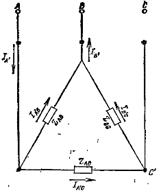 Figure 3. Delta connection of motor windings after phase loss
In the starting mode, the same current will flow through the windings AB as in the three-phase version, and half the current will flow through the windings AC and BC, since these windings are connected in series.
Currents in linear conductors I'a =I'b will be equal to the sum of currents in parallel branches: I'A = I'ab + I'bc = 1.5 Iab
Thus, in the case under consideration, with a phase loss, the starting current in one of the phases will be equal to the starting current with a three-phase supply, and the line current increases less intensively.
To calculate the currents in the event of phase loss after starting the motor, the same method is used as for the "star" circuit. We will assume that the motor develops the same power in both three-phase and single-phase mode.
In this mode of operation, the current in the most loaded phase with a phase loss is doubled compared to the current with a three-phase supply. The current in the line conductor will be Ia 'A = 3Iab, and with a three-phase supply Ia = 1.73 Iab.
It is important to note here that while the phase current increases by a factor of 2, the line current only increases by a factor of 1.73. This is essential because the overcurrent protection reacts to the line currents. The calculations and conclusions regarding the influence of the load factor on the single-phase current with a «star» connection remain valid for the case of a «delta» circuit.
AC and BC phase voltages will depend on the rotor speed. When the rotor is locked Uac '= Ub° C' = Uab / 2
At a rotation speed equal to the synchronous, the symmetrical system of voltages is restored, i.e.ac '= Ub° C' = Uab.
Thus, the AC and BC phase voltages, when the rotation speed is changed from zero to synchronous, will change from a value equal to half the line voltage to a value equal to the line voltage.
The currents and voltages of the motor phases in single-phase operation also depend on the number of motors.
A phase loss often occurs when one of the fuses on the substation or switchgear mains supply has blown. As a result, a group of users are in single-phase mode interacting with each other. The distribution of currents and voltages depends on the power of the individual motors and their load. Different options are possible here. If the power of the electric motors are equal and their load is the same (for example, a group of exhaust fans), then the entire group of motors can be replaced by an equivalent one.
Emergency modes of asynchronous electric motors and methods of their protection

