Potentiometric sensors
A potentiometer sensor is a variable resistor to which a supply voltage is applied, its input value is the linear or angular displacement of the current-collecting contact, and the output value is the voltage taken by this contact, which changes in magnitude as its position changes.
Potentiometric sensors are designed to convert linear or angular displacements into an electrical signal, as well as to reproduce the simplest functional dependencies in automatic and automatic devices of a continuous type.
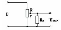
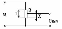 Potentiometric sensor connection diagram
By resistance, potentiometric sensors are divided into
-
lamellas with constant resistance;
-
wire coil with continuous winding;
-
with a resistive layer.
Lamellar potentiometric sensors were used to conduct relatively coarse measurements due to certain design flaws.
In such sensors, constant resistors, selected nominally in a special way, are soldered to the lamellae.
The lamella is a structure with alternating conductive and non-conductive elements on which the collector contact slides.When the current collector is moved from one conducting element to another, the total resistance of the resistors connected to it changes by an amount corresponding to the nominal value of one resistance. The change in resistance can occur over a wide range. The measurement error is determined by the size of the contact pads.
Lamellar potentiometer sensor
Wire potentiometer sensors are designed for more accurate measurements. As a rule, their designs are a frame made of getinax, textolite or ceramics, on which a thin wire is wound in one layer, turns in a turn, on the cleaned surface of which a current collector slides.
The diameter of the wire determines accuracy class potentiometer sensor (high is 0.03-0.1mm, low is 0.1-0.4mm). Wire materials: manganin, fechral, alloys based on noble metals. The slip ring is made of a softer material to prevent the wire from chafing.
The advantages of potentiometer sensors:
-
simplicity of design;
-
small size and weight;
-
high degree of linearity of static characteristics;
-
stability of characteristics;
-
possibility of operation on alternating current and direct current.
Disadvantages of potentiometer sensors:
-
the presence of a sliding contact, which can cause damage due to oxidation of the contact trace, rubbing of turns or bending of the slider;
-
error in operation due to load;
-
relatively small conversion factor;
-
high sensitivity threshold;
-
the presence of noise;
-
susceptibility to electrical erosion under the influence of impulse discharges.
Static characteristic of potentiometric sensors
Static characteristic of an irreversible potentiometric sensor
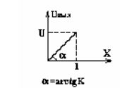
Let us consider as an example a potentiometer sensor with a continuous coil. An AC or DC voltage U is applied to the potentiometer terminals. The input value is the displacement X, the output value is the voltage Uout. For idle mode, the static characteristic of the sensor is linear because the relation is true: Uout = (U / R) r,
where R is the coil resistance; r is the resistance of a portion of the coil.
Given that r / R = x / l, where l is the total length of the coil, we get Uout = (U / l) x = Kx [V / m],
where K is the conversion (transmission) coefficient of the sensor.
Obviously, such a sensor will not respond to a change in the sign of the input signal (the sensor is irreversible). There are schemes that are sensitive to changes in signatures. The static characteristic of such a sensor has the form shown in the figure.
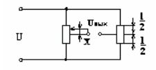
Reversible circuit of a potentiometer sensor
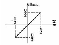
Static characteristic of a reversible potentiometric sensor
The resulting ideal characteristics can differ significantly from the real ones due to the presence of various types of errors:
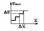
1. Dead zone.
The output voltage varies discretely from turn to turn, i.e. this zone occurs when, for a small input value, Uout does not change.
The magnitude of the voltage jump is determined by the formula: DU = U / W, where W is the number of turns.
The sensitivity threshold is determined by the diameter of the coil wire: Dx = l / W.
Potentiometric sensor for dead band
2. Irregularity of static characteristics due to variability of wire diameter, resistance and winding pitch.
3. An error from backlash that occurred between the axis of rotation of the motor and the guide sleeve (compression springs are used to reduce it).
4.Error due to friction.
At low powers of the element driving the brush of the potentiometer sensor, a stagnation zone may occur due to friction.
Brush pressure must be carefully adjusted.
5. Error due to load influence.
Depending on the nature of the load, an error occurs, both in static and dynamic mode. With an active load, the static characteristic changes. The output voltage value will be determined according to the expression: Uout = (UrRn) / (RRn + Rr-r2)
These. Uout = f (r) depends on Rn. With Rn >> R it can be shown that Uout = (U / R) r;
when Rn is approximately equal to R, the dependence is non-linear and the maximum error of the sensor will be when the slider deviates from (2/3))l. Usually choose Rн / R = 10 … 100. The magnitude of the error at x = (2/3) l can be determined by the expression: E = 4/27η, where η= Rн / R — load factor.
Potentiometric sensor under load
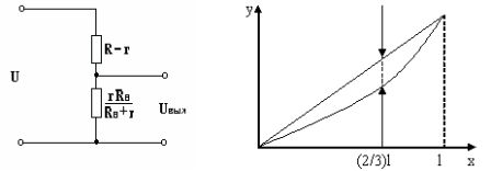 a — Equivalent circuit of a potentiometric sensor with a load, b — Influence of the load on the static characteristic of the potentiometric sensor.
Dynamic characteristics of potentiometric sensors
Transmission function
To derive the transfer function, it is more convenient to take the load current as the output value; it can be determined using the equivalent generator theorem. B = Uout0 / (Rvn + Zn)
Consider two cases:
1. The load is purely active Zn = Rn because Uout0 = K1x In = K1x / (Rin + Rn)
where K1 is the idle speed of the sensor.
Applying the Laplace transform, we obtain the transfer function W (p) = In (p) / X (p) = K1 / (Rin + Rn) = K
In this way, we obtained an inertialess connection, which means that the sensor has all the frequency and time characteristics corresponding to this connection.
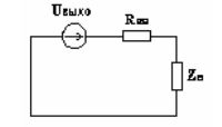
Equivalent circuit
2. Inductive load with an active component.
U = RvnIn + L (dIn / dt) + RnIn
Applying the Laplace transform, we obtain Uoutx (p) = In (p) [(Rvn + pL) + Rn]
Through transformations, one can arrive at a transfer function of the form W (p) = K / (Tp + 1) — an aperiodic connection of the 1st order,
where K = K1 / (Rvn + Rn)
T = L / (Rvn + Rn);
Internal noise of the potentiometer sensor
 As shown, as the brush moves from turn to turn, the output voltage changes abruptly. The error created by stepping is in the form of a sawtooth voltage superimposed on the output voltage of the transfer function, i.e. is noise. If the brush vibrates, the movement also creates noise (interference). The frequency spectrum of vibrational noise is in the audio frequency range.
To eliminate vibrations, pantographs are made of several wires of different lengths folded together. Then the natural frequency of each wire will be different, this prevents the appearance of technical resonance. The level of thermal noise is low, they are taken into account in particularly sensitive systems.
Functional potentiometric sensors
It should be noted that in automation functional transfer functions are often used to obtain nonlinear dependencies. They are constructed in three ways:
-
changing the diameter of the wire along the coil;
-
coil pitch change;
-
the use of a frame with a certain configuration;
-
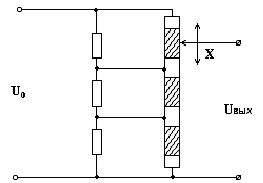
by maneuvering the sections of linear potentiometers with resistances of different sizes.
For example, to obtain a quadratic dependence according to the third method, it is necessary to change the width of the frame linearly, as shown in the figure.
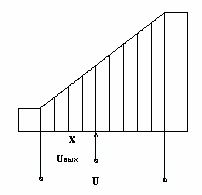
Functional potentiometer sensor
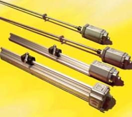
Multi-turn potentiometer
Conventional potentiometer sensors have a limited operating range. Its value is determined by the geometric dimensions of the frame and the number of coil turns. They cannot increase infinitely. Therefore, multi-turn potentiometer sensors have found application, where a resistive element is twisted in a spiral line with several turns, their axis must be rotated several times so that the motor moves from one end of the coil to the other, i.e. the electrical range of such sensors is a multiple of 3600.
The main advantage of multi-turn potentiometers is their high resolution and accuracy, which is achieved due to the large length of the resistive element with small overall dimensions.
Photopotentiometers
Photopotentiometer — is a non-contact analogue of a conventional potentiometer with a resistive layer, the mechanical contact in it is replaced by a photoconductive one, which, of course, increases reliability and service life. The signal from the photopotentiometer is controlled by a light probe that acts as a slider. It is formed by a special optical device and can be displaced as a result of external mechanical action along the photoconductive layer. At the point where the photolayer is exposed, excess (compared to dark) photoconductivity occurs and an electrical contact is made.
Photopotentiometers are divided by purpose into linear and functional.
Functional photopotentiometers allow the spatial movement of the light source to be converted into an electrical signal with a given functional form due to the profiled resistive layer (hyperbolic, exponential, logarithmic).