DC motors
Direct current electric motors are used in these electric drives where a large range of speed control, high accuracy of maintaining the rotational speed of the drive and speed control above the rated speed are required.
How do DC motors work?
The operation of a DC electric motor is based on the phenomenon of electromagnetic induction… It is known from the basics of electrical engineering that a current-carrying conductor is placed magnetic field, the force determined by the left rule acts:
F = BIL,
where I is the current flowing through the wire, V is the induction of the magnetic field; L is the length of the wire.
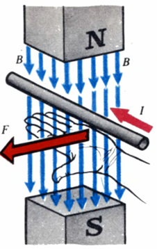
When the wire crosses the machine's magnetic field lines inwards it is induced electromotive force, which, in relation to the current in the conductor, is directed against it, therefore it is called opposite or opposite (contra-d. d. s). The electrical power in the motor is converted into mechanical power and is partially spent heating the wire.
 Structurally, all DC electric motors consist of an inductor and an armature separated by an air gap.
Inductor electric motor direct current serves to create a stationary magnetic field of the machine and consists of a frame, main and additional poles. The frame is used to fix the main and auxiliary poles and is an element of the magnetic circuit of the machine. Exciting coils are located on the main poles designed to create a magnetic field of the machine, on additional poles - a special coil to improve commutation conditions.
Anchor electric motor direct current consists of the magnetic system assembled from individual sheets, the working coil placed in the grooves, and collector serves for the approach to the working coil constant current.
A collector is a cylinder impaled on the engine shaft and selected from isolated friend by friend on copper plates. The collector has cocking protrusions, to which the ends of the sections are soldered coil armatures. Collecting current from the collector is done using brushes that provide sliding contact with the collector. Brushes fixed in brush holders that hold them in a certain position and provide the necessary pressure of the brush on the surface of the collector. Brushes and brush holders are fixed on the traverse, connected to the body electric motor.
Commutation in DC electric motors
When an electric motor is running, the DC brushes sliding on the surface of the rotating collector pass successively from one collector plate to another. In this case, the parallel sections of the armature winding are switched and the current in them changes. The change in current occurs while the coil turn is short-circuited by the brush. This switching process and related phenomena are called commutation.
At the moment of switching, e is induced in the short-circuited section of the coil under the influence of its own magnetic field. etc. v. self-induction. The resulting e. etc. c. causes additional current in the short circuit, which creates an uneven distribution of current density on the contact surface of the brushes. This circumstance is considered to be the main reason for the collector arcing under the brush. The quality of the commutation is judged by the degree of sparking below the trailing edge of the brush and is determined by the scale of the degree of sparking.
Methods of excitation electric motors direct current
Excited by electric machines, I understand the creation of a magnetic field in them, necessary for the operation of an electric motor... Circuits for excitation electric motors direct current shown in the figure.
Circuits for excitation of DC motors: a — independent, b — parallel, c — series, d — mixed
According to the method of excitation, DC electric motors are divided into four groups:
1. Independently excited where the NOV excitation coil is powered by an external DC source.
2. With parallel excitation (shunt), in which the excitation winding SHOV is connected in parallel with the supply source of the armature winding.
3. With series excitation (series), where the IDS excitation winding is connected in series with the armature winding.
4. Mixed-excitation (combined) motors that have series IDS and parallel SHOV of the excitation winding.
Types of DC motors
DC motors differ primarily in the nature of the excitation. Motors can be of independent, series and mixed excitation.In parallel, the excitement can be neglected. Even if the field winding is connected to the same network from which the armature circuit is fed, then also in this case the excitation current does not depend on the armature current, since the supply network can be considered as a network of infinite power, and the voltage it's permanent.
The field winding is always connected directly to the grid and therefore the introduction of additional resistance in the armature circuit has no effect on the excitation mode. The specifics that it exists with parallel excitation in the generators, it can't be here.
Low power DC motors often use permanent magnet excitation. At the same time, the circuit for turning on the motor is significantly simplified, copper consumption is reduced. It should be noted, however, that although the field winding is switched off, the dimensions and weight of the magnetic system are not lower than with electromagnetic excitation of the machine.
The properties of engines are largely determined by their system. excitement.
The larger the size of the engine, the greater the natural torque and, accordingly, the power. Therefore, with a higher rotation speed and the same dimensions, you can get more engine power. In this regard, as a rule, DC motors are designed, especially with low power at high speed — 1000-6000 rpm.
However, you should keep in mind that the speed of rotation of the working bodies of the production machines is significantly lower. Therefore, a gearbox must be installed between the engine and the working machine.The higher the engine speed, the more complex and expensive the gearbox becomes. In high power installations, where the gearbox is an expensive unit, the engines are designed at significantly lower speeds.
It should also be borne in mind that a mechanical gearbox always introduces a significant error. Therefore, in precision installations, it is desirable to use low-speed motors, which could be connected to working bodies directly or through the simplest transmission. In this connection, the so-called motors with high torque at low rotational speeds appeared. These motors are widely used in metal-cutting machines, where they are articulated with displacement bodies without any intermediate connections using ball screws.
Electric motors also differ in design when signs related to the conditions of their operation. For normal conditions, so-called open and protected engines are used, air-cooled rooms in which they are installed.
Air is blown through the ducts of the machine by means of a fan placed on the motor shaft. Closed motors cooled by an external finned surface or an external air stream are used in aggressive environments. Finally, special explosive atmosphere engines are available.
Specific requirements for the design of the engine are presented when it is necessary to ensure high performance — a rapid flow of acceleration and deceleration processes. In this case, the engine must have a special geometry — a small diameter of the armature with its long length.
To reduce the inductance of the winding, it is not laid in the channels, and on the surface of a smooth armature.The coil is fixed with adhesives such as epoxy resin. With low coil inductance it is essential that commutation conditions of the collector are improved, there is no need for additional poles, a collector of smaller dimensions can be used. The latter further reduces the moment of inertia of the motor armature.
Even greater possibilities for reducing mechanical inertia provide the use of a hollow armature, which is a cylinder of insulating material. On the surface of this cylinder is located a winding made by printing, stamping or by drawing on a template on a special machine. The coil is fixed with adhesive materials.
Inside a rotating cylinder to create paths, a steel core is necessary for the passage of the magnetic flux. In motors with smooth and hollow armatures, due to an increase in the gaps in the magnetic circuit due to the introduction of windings and insulating materials into them, the required magnetizing force to conduct the required magnetic flux increases significantly. Accordingly, the magnetic system turns out to be more developed.
Low inertia motors also include disk armature motors. Disks on which the windings are applied or glued, made of a thin insulating material that does not deform, for example glass. A magnetic system in the bipolar version consists of two clamps, one of which houses the excitation coils. Due to the low inductance of the armature winding, the machine, as a rule, does not have a collector, and the current is removed by brushes directly from the winding.
It should also be mentioned about the linear motor, which does not provide rotary motion and translational.It represents the motor, the magnetic system on which it is located and the poles are mounted on the line of motion of the armature and the corresponding worker body of the machine. The anchor is usually designed as a low inertia anchor. The size and cost of the motor is large, as a significant number of poles are required to provide movement along a given section of road.
Starting DC motors
At the initial moment of starting the motor, the armature is stationary and opposite. etc. c. ivoltage in the armature is equal to zero, therefore Ip = U / Rya.
The resistance of the armature circuit is small, so the inrush current exceeds 10 — 20 times or more nominal. This can cause significant electrodynamic efforts in the armature winding and its excessive overheating, due to which the motor begins to be used starting rheostats — active resistances included in the armature circuit.
Motors up to 1 kW can be started directly.
The resistance value of the starting rheostat is selected according to the permissible starting current of the motor. The rheostat is made in stages to improve the smoothness of starting the electric motor.
At the beginning of the start, the entire resistance of the rheostat is introduced. As the anchor speed increases, there is a counter-e. d. s, which limits the inrush currents. Gradually removing step by step the resistance of the rheostat from the armature circuit, the voltage supplied to the armature increases.
Speed control electric motor direct current
DC motor speed:
where U is the supply voltage; Iya — armature current; Ri is the armature resistance of the circuit; kc — coefficient characterizing the magnetic system; F is the magnetic flux of the electric motor.
From the formula, it can be seen that the speed of rotation electric motor direct current can be adjusted in three ways: by changing the excitation flux of the electric motor, changing the voltage supplied to the electric motor, and changing the resistance in armature circuits.
The first two control methods have received the most widespread use, the third method is rarely used: it is uneconomical and the motor speed significantly depends on load fluctuations. The resulting mechanical properties are shown in Fig.
Mechanical characteristics of a DC motor with different speed control methods
The bold line is the natural dependence of the speed on the shaft torque, or, what is the same, on the armature current. The straight line with natural mechanical characteristics deviates somewhat from the horizontal dashed line. This deviation is called instability, non-rigidity, sometimes statism. A group of non-parallel straight lines I corresponds to speed regulation by excitation, parallel straight lines II are obtained as a result of changing the armature voltage, finally fan III is the result of introducing active resistance into the armature circuit.
The magnitude of the excitation current of a DC motor can be controlled using a rheostat or any device whose resistance can be varied in magnitude, such as a transistor. As the resistance in the circuit increases, the field current decreases, the motor speed increases.At When the magnetic flux weakens, the mechanical characteristics are above the natural ones (ie, above the characteristics in the absence of a rheostat). An increase in engine speed leads to an increase in sparking under the brushes. In addition, when the electric motor operates with weakened flux, the stability of its operation decreases, especially with variable shaft loads. Therefore, speed control limits in this way do not exceed 1.25 — 1.3 times the nominal.
Voltage regulation requires a constant current source such as a generator or converter. Similar regulation is used in all industrial electric drive systems: generator - direct current drive (G - DPT), electric machine amplifier - DC motor (EMU - DPT), magnetic amplifier - DC motor (MU - DPT), thyristor converter — DC motor (T — DPT).
Stop electric motors direct current
Three methods of braking are used in electric drives with DC electric motors: dynamic, regenerative and oppositional braking.
Dynamic braking DC motor is done by short-circuiting the armature winding of the motor or by resistor… In which a DC motor starts working as a generator, converting stored mechanical energy into electrical energy. This energy is released as heat in the resistance to which the armature winding is closed. Dynamic braking ensures precise engine braking.
 Regenerative braking DC motor performs when connected to the mains electric motor is rotated by the drive mechanism at a speed exceeding the ideal idle speed. Then d.etc.s induced in the motor winding will exceed the line voltage value, the current in the motor winding will reverse direction. An electric motor goes to work in generator mode, giving energy to the network. At the same time, a braking moment occurs on its shaft. Such a mode can be obtained in the drives of lifting mechanisms when lowering the load, as well as when regulating the speed of the motor and during braking processes in electric drives with direct current.
Regenerative braking of a DC motor is the most economical method, since in this case the electricity is returned to the grid. In the electric drive of metal-cutting machines, this method is used for speed control in the G — DPT and EMU — DPT systems.
Stopping the opposition DC motor is done by changing the polarity of the voltage and current in the armature winding. When the armature current interacts with the magnetic field of the excitation coil, a braking torque is created, which decreases with a decrease in the speed of rotation of the electric motor. When the speed of an electric motor decreases to zero, the electric motor must be disconnected from the network, otherwise it will start to rotate in the opposite direction.