Power diodes
Electron hole compound
The principle of operation of most semiconductor devices is based on phenomena and processes that occur at the boundary between two regions of a semiconductor with different types of electrical conductivity - electron (n-type) and hole (p-type). In the n-type region, electrons predominate, which are the main carriers of electric charges, in the p-region, these are positive charges (holes). The boundary between two regions of different conductivity types is called a pn junction.
Functionally, the diode (Fig. 1) can be considered an uncontrolled electronic switch with one-sided conduction. A diode is in the conducting state (closed switch) if a forward voltage is applied to it.

Rice. 1. Conventional graphic designation of the diode
The current through the iF diode is determined by the parameters of the external circuit, and the voltage drop in the semiconductor structure is of little importance. If a reverse voltage is applied to the diode, it is in a non-conducting state (open switch) and a small current flows through it. The voltage drop across the diode in this case is determined by the parameters of the external circuit.
Protection of the diodes
The most typical causes of electrical failures of a diode are a high rate of rise of the forward current diF / dt when on, overvoltage when off, exceeding the maximum value of the forward current and breaking the structure with an unacceptably high reverse voltage.
At high values of diF / dt, an uneven concentration of charge carriers appears in the diode structure and, as a result, local overheating with subsequent damage to the structure. The main reason for the high values of diF / dt is the small inductance in a circuit containing a forward voltage source and an on diode. To reduce the values of diF / dt, an inductance is connected in series with the diode, which limits the rate of rise of the current.
To reduce the values of the amplitudes of the voltages applied to the diode when the circuit is turned off, a series-connected resistor R is used and capacitor C is the so-called RC circuit connected in parallel with the diode.
To protect the diodes from current overloads in emergency modes, high-speed electrical fuses are used.
The main types of power diodes
According to the main parameters and purpose, diodes are usually divided into three groups: general purpose diodes, fast recovery diodes and Schottky diodes.
General purpose diodes
This group of diodes is distinguished by high values of reverse voltage (from 50 V to 5 kV) and forward current (from 10 A to 5 kA). The massive semiconductor structure of diodes degrades their performance. Therefore, the reverse recovery time of diodes is usually in the range of 25-100 μs, which limits their use in circuits with frequencies above 1 kHz.As a rule, they work in industrial networks with a frequency of 50 (60) Hz. The continuous voltage drop across the diodes of this group is 2.5-3 V.
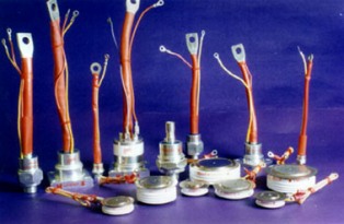
Power diodes come in different packages. The most widespread are two types of execution: a pin and a tablet (Fig. 2 a, b).
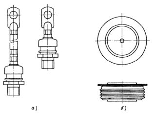
Rice. 2. Construction of diode bodies: a — pin; b — tablet
Fast recovery diodes. In the production of this group of diodes, various technological methods are used to reduce the time of reverse recovery. In particular, silicon doping using the diffusion method of gold or platinum is used. This makes it possible to reduce the recovery time to 3-5 μs. However, this reduces the allowable values of forward current and reverse voltage. The permissible current values are from 10 A to 1 kA, reverse voltage — from 50 V to 3 kV. The fastest diodes have a reverse recovery time of 0.1-0.5 μs. Such diodes are used in pulse and high-frequency circuits with frequencies of 10 kHz and higher. The design of diodes in this group is similar to that of general purpose diodes.
Diode Schottky
The principle of operation of Schottky diodes is based on the properties of the transition region between the metal and the semiconductor material. For power diodes, a layer of n-type depleted silicon is used as a semiconductor. In this case, there is a negative charge in the transition region on the metal side and a positive charge on the semiconductor side.
A peculiarity of Schottky diodes is that the forward current is due to the movement of only the main carriers — electrons. The lack of minority carrier accumulation significantly reduces the inertia of Schottky diodes.The recovery time is usually no more than 0.3 μs, the forward voltage drop is about 0.3 V. The reverse current values in these diodes are 2-3 orders of magnitude higher than in p-n-junction diodes. The limiting reverse voltage is usually no more than 100 V. They are used in high-frequency and low-voltage pulse circuits.