Step-down transformers for powering control and signal circuits
To power control circuits, local lighting and signal complex circuits in order to increase the reliability of the operation of electrical devices and ensure safer maintenance of electrical equipment, they use step-down transformers.
Step-down transformers of the OSM, TSZI, OSOV and TBS2 series are most common in the control and signaling circuits of installations, metal-cutting machines and machines.
Step-down transformers for control circuits, local lighting and signaling must be installed in places protected from the ingress of dust, water and oil (in control cabinets, niches). Transformers must be installed in such a way that accidental touching of live parts by service personnel cannot occur. Transformers must be grounded with a copper wire with a cross-section of at least 2.5 mm. Fixing the transformer does not eliminate the need to connect the ground wire.
Transformers down TSZI
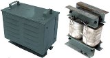 TSZI-1.6, TSZI-2.5, TSZI-4.0 are three-phase step-down transformers (transformer windings are made of copper or aluminum) with natural air cooling. Designed to safely power power tools or lamps for local lighting with a frequency of 50 Hz. The transformers are manufactured in UHL climatic design. Heating class — «B». Protective version (in case).
Step-down transformers OSOV-0.25
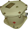 OSOV-0.25-single-phase step-down transformer, dry, waterproof design. It is used in non-hazardous gas and dust mines, in other industries to power lamps for local lighting and power tools. Service life — not less than 12 years.
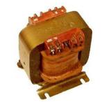
Step-down transformers type OSVM
OSVM-1-OM5, OSVM-1.6-OM5, OSVM-2.5-OM5, OSVM-4-OM5 - single-phase step-down transformers in protective housing (IP45). Designed to power various electrical equipment in general industrial electrical installations. Service life — at least 25 years.
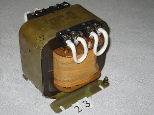
Step-down transformers OSM1
 Single-phase transformers of the OSM series power 0.63 — 4.0 kVA, version U3, connected to an alternating current of 50 Hz with a nominal voltage of up to 660 V, are intended to supply control circuits of local lighting, signaling and rectifiers assembled from a full-wave rectifier circuit.
OSM transformers are designed for indoor operation under the following conditions:
-
non-explosive environment;
-
height above sea level — not more than 1000m;
-
ambient temperature from minus 45°C to plus 40°C.
The necessary contact protection, moisture protection and overload protection are provided by the installation in which the transformer is built.
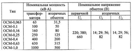
The symbol of the transformer is deciphered as follows: O — single-phase, C — dry, M — multifunctional. The numbers after the letters indicate the rated power in kVA. Climatic version — U, T, HL and placement category — 3. Winding connection diagrams and technical data of transformers of the OSM series are shown in fig. 1 and in tables 1 — 4.
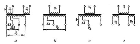
Figure 1 Connection diagrams of the windings of the transformers of the OSM series: a — for powering control, signal and lighting circuits (version 1), b — for powering rectifiers, control circuits (version 2), c — for powering lighting circuits or control circuits (version 3), g — for operation in dynamic brake circuits (version 4)
Table 1. Technical data of OCM series transformers for powering control circuits, signaling and local lighting
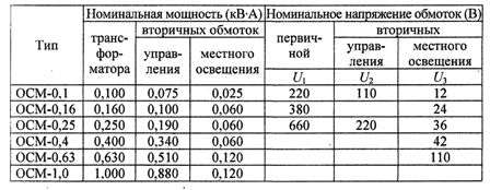
Table 2. Technical data of transformers of the OCM series for powering rectifiers of the control circuit
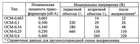
Table 3. Technical data of transformers of the OCM series for powering local lighting circuits or control circuits
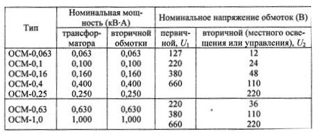
Table 4. Technical data of OCM series transformers for operation in dynamic braking circuits
Selection of control transformers
A feature of the calculation of control transformers is the need to take into account the peak nature of the load, because when it is switched on magnetic starters, contactors, electromagnets their windings consume a current many times higher than the nominal one. This leads to a voltage drop in the circuit, which should not be lower than 85% of the nominal mains voltage. UNS.
When choosing a control transformer, proceed from the following conditions:
1) Rated power of the transformer Сn (V-A) in continuous mode must be not less than the total power consumed by the devices when they are simultaneously in (working) state:

2) Voltage drop in the transformer caused by the load of the operating dUp and dU included in the electrical receivers must be at least the permissible dUt = dUр + dUv
Allowed deviation of the supply voltage of the transformer within (0.85-1.1) Uns, As a result you can assume dUt <0.15 UNS
For practical calculation, it is convenient to use the following formula for determining the power of control transformers based on the allowable reduction dUT:
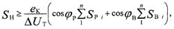
— where ek is the voltage drop in the coil (you can take ek — 15% Uns, cosφp is the power factor of working electric receivers (usually cosφп = 0.2 — 0.4); cosφв — power factor of switched-on electric receivers (typically cosφs = 0.6 — 0.8).
Transformer power for control circuits can also be determined by the following formula:
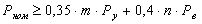 where m is the largest number of simultaneously switched-on devices, Ru is the power consumed by each individual device in the switched-on state (taken from the catalog), n is the number of simultaneously switched-on devices with the largest number of switches on; Pv - power consumed by each device when switched on - starting power (taken from the catalog - bulbs and direct current devices are not taken into account, since they have no starting current).
The nominal power of the transformer is selected according to the larger of the values obtained in the calculation. This calculation allows you to determine the type of transformer according to the table. 1-4.