Thermoelectric converters (thermocouples)
 How a thermocouple works
Already in 1821, Seebeck discovered a phenomenon named after him, which consists in the fact that e. Appears in a closed circuit consisting of different conducting materials. etc. (so-called thermo-EMC) if the contact points of these materials are maintained at different temperatures.
In its simplest form, when an electrical circuit consists of two different conductors, it is called a thermocouple, or thermocouple.
The essence of the Seebeck phenomenon lies in the fact that the energy of free electrons, which cause the appearance of an electric current in wires, is different and changes differently with temperature. Therefore, if there is a temperature difference along the wire, the electrons at its hot end will have higher energies and velocities compared to the cold end, causing an electron flow from the hot end to the cold end in the wire. As a result, charges will accumulate at both ends — negative on cold and positive on hot.
Since these charges are different for different wires, then when two of them are connected in a thermocouple, a differential thermocouple will appear. etc. c. To analyze the phenomena occurring in the thermocouple, it is convenient to assume that the thermocouple generated in it. etc. c. E is the sum of two contact electromotive forces e, occurring at the places of their contact and are a function of the temperature of these contacts (Fig. 1, a).
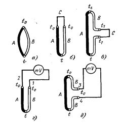
Rice. 1. Diagram of a two- and three-wire thermoelectric circuit, a diagram for connecting an electrical measuring device to the junction and a thermoelectrode with a thermocouple.
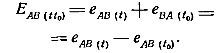
The thermoelectromotive force arising in a circuit of two different conductors is equal to the difference in the electromotive forces at their ends.
From this definition it follows that at equal temperatures at the ends of the thermocouple, its thermoelectric power. etc. s will be zero. An extremely important conclusion can be drawn from this, which makes it possible to use a thermocouple as a temperature sensor.
 The electromotive force of a thermocouple will not be changed by the introduction of a third wire in its circuit if the temperatures at its ends are the same.
This third wire can be included both in one of the junctions and in the section of one of the wires (Fig. 1.6, c). This conclusion can be extended to several wires introduced into the thermocouple circuit, as long as the temperatures at their ends are the same.
Therefore, a measuring device (also consisting of wires) and connecting wires leading to it can be included in the thermocouple circuit without causing a change in the thermoelectric power developed by it. e.c, only if the temperatures of points 1 and 2 or 3 and 4 (Fig. 1, d and e) are equal. In this case, the temperature of these points may differ from the temperature of the terminals of the device, but the temperature of both terminals must be the same.
If the resistance of the thermocouple circuit remains unchanged, the current flowing through it (and therefore the reading of the device) will depend only on the thermoelectric power developed by it. d. from, that is, from the temperatures of the working (hot) and free (cold) ends.
Also, if the temperature of the free end of the thermocouple is kept constant, the meter reading will depend only on the temperature of the working end of the thermocouple. Such a device will directly indicate the temperature of the working junction of the thermocouple.
Therefore, a thermoelectric pyrometer consists of a thermocouple (thermoelectrodes), a direct current meter and connecting wires.
The following conclusions can be drawn from the above.
1. The method of manufacturing the working end of the thermocouple (welding, soldering, twisting, etc.) does not affect the thermoelectric power developed by it. etc. with, if only the dimensions of the working end are such that the temperature at all its points is the same.
2. Because the parameter measured by the device is not thermoelectric. with and the thermocouple circuit current, it is necessary that the operating circuit resistance remains unchanged and equal to its value during calibration.But since it is practically impossible to do this, since the resistance of the thermoelectrodes and connecting wires changes with temperature, one of the main errors of the method arises: the error of the mismatch between the resistance of the circuit and its resistance during calibration.
To reduce this error, devices for thermal measurements are made with high resistance (50-100 Ohm for rough measurements, 200-500 Ohm for more accurate measurements) and with a low temperature electrical coefficient, so that the total resistance of the circuit (and , therefore, the relationship between current and — e. d. s.) varies to a minimum with fluctuations in ambient temperature.
3. Thermoelectric pyrometers are always calibrated at a well-defined temperature of the free end of the thermocouple — at 0 ° C. Usually this temperature differs from the calibration temperature in operation, as a result of which the second main error of the method occurs: the error in the temperature of the free thermocouple end.
Since this error can reach tens of degrees, it is necessary to make an appropriate correction of the readings of the device. This correction can be calculated if the temperature of the risers is known.
Since the temperature of the free end of the thermocouple during calibration is equal to 0 ° C, and in operation it is usually above 0 ° C (the free ends are usually in the room, they are often located near the oven whose temperature is measured), the pyrometer gives an underestimate compared to the actual measured temperature, the indication and value of the latter must be increased by the correction value.
This is usually done graphically. This is due to the fact that there is usually no proportionality between the thermosets.etc. pp. and temperature. If the relationship between them is proportional, then the calibration curve is a straight line and in this case the correction for the temperature of the free end of the thermocouple will be directly equal to its temperature.
Design and types of thermocouples
The following requirements apply to the thermoelectrode materials:
1) high thermoelectricity. etc. v. and close to the proportional nature of its change from temperature;
2) heat resistance (non-oxidization at high temperatures);
3) constancy of physical properties over time within the measured temperatures;
4) high electrical conductivity;
5) low-temperature coefficient of resistance;
6) the possibility of production in large quantities with constant physical properties.
The International Electrotechnical Commission (IEC) has defined some standard types of thermocouples (standard IEC 584-1). Elements have indices R, S, B, K, J, E, T according to the range of temperatures measured.
In industry, thermocouples are used to measure high temperatures, up to 600 — 1000 — 1500˚С. An industrial thermocouple consists of two refractory metals or alloys. The hot junction (marked with the letter «G») is placed in the place where the temperature is measured, and the cold junction («X») is located in the area where the measuring device is located.
The following standard thermocouples are currently in use.
 Platinum-rhodium-platinum thermocouple. These thermocouples can be used to measure temperatures up to 1300 °C for long-term use and up to 1600 °C for short-term use, provided they are used in an oxidizing atmosphere.At medium temperatures, the platinum-rhodium-platinum thermocouple has proven to be very reliable and stable, which is why it is used as an example in the range of 630-1064 ° C.
Chrome-alumel thermocouple. These thermocouples are designed to measure temperatures for long-term use up to 1000 ° C and for short-term use up to 1300 ° C. They work reliably within these limits in an oxidizing atmosphere (if there are no corrosive gases), because when heated on the surface of the electrodes, a thin protective oxide film that prevents oxygen from penetrating the metal.
Chromel-Copel Thermocouple… These thermocouples can measure temperatures up to 600°C for a long time and up to 800°C for a short time. They work successfully in both oxidizing and reducing atmospheres, as well as in vacuum.
Iron Copel thermocouple... The measurement limits are the same as for chromel-copel thermocouples, the operating conditions are the same. It gives less thermo. etc. vs. compared to the XK thermocouple: 30.9 mV at 500 ° C, but its dependence on temperature is closer to proportional. A significant drawback of the LC thermocouple is the corrosion of its iron electrode.
Copper-copper thermocouple... Since copper in an oxidizing atmosphere begins to intensively oxidize already at 350 ° C, the range of application of these thermocouples is 350 ° C for a long time and 500 ° C for a short time. In vacuum, these thermocouples can be used up to 600 °C.
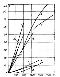
Thermo-e dependence curves. etc. of temperature for the most common thermocouples. 1 — chromel-bastard; 2 — iron-bastard; 3 — copper-bastard; 4 — TGBC -350M; 5 — TGKT-360M; 6 — chromel-alumel; 7-platinum-rhodium-platinum; 8 — TMSV-340M; 9 — PR -30/6.
The resistance of the thermoelectrodes of standard thermocouples made of base metals is 0.13-0.18 ohms per 1 m of length (both ends), for platinum-rhodium-platinum thermocouples 1.5-1.6 ohms per 1 m. Allowable thermoelectric power deviations. etc. from calibration for non-noble thermocouples are ± 1%, for platinum-rhodium-platinum ± 0.3-0.35%.
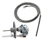
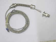
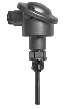
The standard thermocouple is a rod with a diameter of 21-29 mm and a length of 500-3000 mm. On the top of the protective tube is placed a stamped or cast (usually aluminum) head with a carbolite or bakelite plate, into which two pairs of wires are pressed with screw clamps connected in pairs. The thermoelectrode is attached to one terminal, and to the other is connected a connecting wire that leads to the measuring device. Sometimes the connecting wires are enclosed in a flexible protective hose. If it is necessary to seal the hole in which the thermocouple is installed, the latter is provided with a threaded fitting. For bathtubs, thermocouples are also made with an elbow shape.
Laws of thermocouples
Internal temperature law: The presence of a temperature gradient in a homogeneous conductor does not lead to the appearance of an electric current (no additional EMF occurs).
The law of intermediate conductors: Let two homogeneous conductors of metals A and B form a thermoelectric circuit with contacts at temperatures T1 (hot junction) and T2 (cold junction). A wire of metal X is included in the rupture of wire A and two new contacts are formed. «If the temperature of wire X is the same throughout its length, then the resulting EMF of the thermocouple will not change (no EMF arises from additional junctions).»