Rectifier diodes
 Diode - a two-electrode semiconductor device with one p-n junction, which has one-sided current conduction. There are many different types of diodes—rectifier, pulse, tunnel, reverse, microwave diodes, as well as zener diodes, varicaps, photodiodes, LEDs, and more.
Rectifier diodes
The operation of the rectifier diode is explained by the properties of the electrical p — n junction.
Near the border of two semiconductors, a layer is formed that is devoid of mobile charge carriers (due to recombination) and has a high electrical resistance — the so-called Blocking layer. This layer determines the contact potential difference (potential barrier).
If an external voltage is applied to the p — n junction, creating an electric field in the direction opposite to the field of the electric layer, then the thickness of this layer will decrease and at a voltage of 0.4 — 0.6 V the blocking layer will disappear and the current will increased significantly (this current is called direct current).
 When an external voltage of different polarity is connected, the blocking layer will increase and the resistance of the p — n junction will increase, and the current due to the movement of minority charge carriers will be negligible even at relatively high voltages.
The forward current of the diode is created by the major charge carriers and the reverse current by the minority charge carriers. A diode passes positive (forward) current in the direction from the anode to the cathode.
In fig. 1 shows the conventional graphic designation (UGO) and characteristics of rectifier diodes (their ideal and actual current-voltage characteristics). The apparent discontinuity of the diode current-voltage characteristic (CVC) at the origin is associated with different current and voltage scales in the first and third quadrants of the graph. Two diode outputs: anode A and cathode K in UGO are not specified and are shown in the figure for explanation.
The current-voltage characteristic of a real diode shows the region of electrical breakdown, when for a small increase in reverse voltage the current increases sharply.
Electrical damage is reversible. When returning to the working area, the diode does not lose its properties. If the reverse current exceeds a certain value, then the electrical failure will become irreversible thermal with the failure of the device.
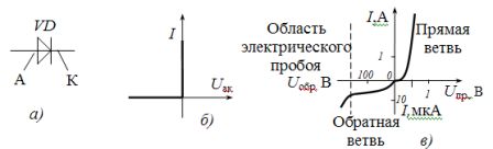
Rice. 1. Semiconductor rectifier: a — conventional graphical representation, b — ideal current-voltage characteristic, c — real current-voltage characteristic
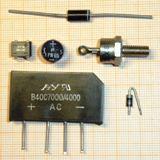
The industry mainly produces germanium (Ge) and silicon (Si) diodes.
Silicon diodes have low reverse currents, higher operating temperature (150 — 200 ° C vs. 80 — 100 ° C), withstand high reverse voltages and current densities (60 — 80 A / cm2 vs. 20 — 40 A / cm2) . In addition, silicon is a common element (unlike germanium diodes, which is a rare earth element).
 The advantages of germanium diodes include a low voltage drop when a direct current flows (0.3 — 0.6 V vs. 0.8 — 1.2 V). In addition to the semiconductor materials listed, gallium arsenide GaAs is used in microwave circuits.
According to the production technology, semiconductor diodes are divided into two classes: point and planar.
Point diodes form an n-type Si or Ge plate with an area of 0.5 — 1.5 mm2 and a steel needle forming a p — n junction at the contact point. As a result of the small area, the junction has a low capacitance, therefore such a diode can work in high-frequency circuits. But the current through the junction cannot be large (usually no more than 100 mA).
A planar diode consists of two connected Si or Ge plates with different electrical conductivities. The large contact area results in a large junction capacitance and a relatively low operating frequency, but the current flowing can be large (up to 6000 A).
The main parameters of rectifier diodes are:
- maximum allowable forward current Ipr.max,
- maximum allowable reverse voltage Urev.max,
- maximum permissible frequency fmax.
According to the first parameter, rectifier diodes are divided into diodes:
- low power, constant current up to 300 mA,
- average power, direct current 300 mA — 10 A,
- high power — power, the maximum forward current is determined by the class and is 10, 16, 25, 40 — 1600 A.
Pulse diodes are used in low power circuits with a pulse character of the applied voltage. A distinctive requirement for them is the short transition time from the closed state to the open state and vice versa (typical time 0.1 — 100 μs). UGO pulse diodes are the same as rectifier diodes.
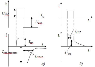
Fig. 2. Transient processes in pulse diodes: a — the dependence of the current when switching the voltage from direct to reverse, b — the dependence of the voltage when a current pulse passes through the diode
Specific parameters of pulse diodes include:
- recovery time Tvosst
- this is the time interval between the moment when the diode voltage switches from forward to reverse and the moment when the reverse current decreases to a given value (Fig. 2, a),
- the settling time Tust is the time interval between the beginning of the direct current of a given value through the diode and the moment when the voltage on the diode reaches 1.2 of the value in the steady state (Figure 2, b),
- the maximum recovery current Iobr.imp.max., equal to the largest value of the reverse current through the diode after switching the voltage from forward to reverse (Fig. 2, a).
Inverted diodes obtained when the concentration of impurities in the p- and n-regions is greater than that of conventional rectifiers. Such a diode has a low resistance to the forward current during reverse connection (Fig. 3) and a relatively high resistance during direct connection. Therefore, they are used in the correction of small signals with a voltage amplitude of several tenths of a volt.
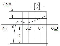
Rice. 3. UGO and VAC of inverted diodes
Schottky diodes obtained by metal-semiconductor transition.In this case, low-resistance n-silicon (or silicon carbide) substrates with a high-resistance thin epitaxial layer of the same semiconductor are used (Fig. 4).
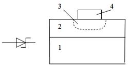 Rice. 4. UGO and the structure of the Schottky diode: 1 — initial silicon crystal with low resistance, 2 — epitaxial layer of silicon with high resistance, 3 — space charge region, 4 — metal contact
A metal electrode is applied to the surface of the epitaxial layer, which provides rectification but does not inject minority carriers into the core region (most often gold). Therefore, in these diodes there are no such slow processes as accumulation and resorption of minority carriers in the base. Therefore, the inertia of Schottky diodes is not high. It is determined by the value of the barrier capacitance of the rectifier contact (1 — 20 pF).
In addition, the series resistance of Schottky diodes is significantly lower than that of rectifier diodes because the metal layer has a low resistance compared to any, even highly doped, semiconductor. This allows the use of Schottky diodes to rectify significant currents (tens of amperes). They are generally used in switching secondaries to rectify high frequency voltages (up to several MHz).
Potapov L.A.