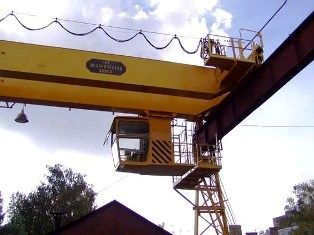
Power supply for crane installations
 Electrical power is supplied to the valves from a common AC network or from DC converters. Using a cable from a separate switch or automatic machine, the main contact wires are energized — cartslaid along the crane tracks. The number of main contact wires with alternating current is three, with direct current - two. In some cases, instead of the main contact wires, for example, in explosive stores, a current conductor using a flexible cable is used.
From the main contact wires using sliding current collectors, the voltage is supplied to a protective panel installed in the crane cabin. Hoist and trolley motors and brake solenoids are powered by overhead wires attached to the bridge and called auxiliary wires. Contact wires are usually made of profiled steel with a circular cross-section, angle, channel or rail. Copper is used relatively rarely and only as utility carts.
Please note that the wiring of the taps is carried out with PRG-500, PRTO-500 wires, which are laid in steel thin-walled pipes, closed boxes or in an open way.Armored wires PRP, PRShP and cables without jute insulation SRG-500, SRBG-500 are also used for installation of cranes. It is not recommended to mount the SRG cable on moving parts of lifting and transport mechanisms, as the lead sheath of the cable is quickly destroyed by vibration.
The smallest cross-section of the conductor in terms of mechanical strength is 2.5 mm2. On the control panels, flat busbars are used instead of wires with a cross section of more than 25-35 mm2. The flexible wires, which find some application on faucets, are made with SHRPS brand copper wire hose and rubber insulation. In severe working conditions with significant mechanical effort, the GRShS cable is used, as well as the ship's cable in the NRShM hose sheath.
The selection of contact wires is done according to the permissible load current, followed by checking the wire for voltage drop. The conductor is selected with a uniform cross-section along the entire length of the movement of the mechanism. The permissible loads for the various types of contact wires are given in the reference tables.
Accurate determination of the estimated current flowing through the contact wires is difficult due to sharp fluctuations crane motor loads… There are several approximate methods for determining the design current, which are mainly based on many years of experience in the operation of crane installations.
The determination of the power consumed by the network and then the estimated current of the contact wires can be carried out, for example, based on the formula:

where P is the power consumed by the network, kW; P3 — installed power of the three largest engines in the group at duty cycle = 25%, kW; Pc — total power of all engines of the group at duty cycle = 25%, kW; c, b — experimental coefficients; for most taps c = 0.3; b = 0.06 ÷ 0.18.
Estimated current can be found for taps operating on AC and DC, respectively, according to the formulas:


where I is the rated current, A; Un — memorial network voltage, V; cosφ is the average power factor of the crane motors; in the calculations cos φ = 0.7.
The current found by the formulas should not exceed the long-term allowable current of the wires

During the operation of the crane, the voltage at the terminals of the crane motor should not be lower than 85% of the rated voltage. At lower voltage, the maximum torque for AC motors is unacceptably reduced. In addition, the operation of contactors and brake solenoids becomes unreliable. The calculation of the entire tap network should be done so that at start-up and operating currents the voltage loss in the tap network does not exceed 8-12%. Network losses can be distributed as follows:
Main contact wires — 3 — 4%
Mains for contact wires — 4 — 5%
Network in the tap — 1 — 3%
For infrequent starting installations, the maximum allowable voltage drop should not exceed 15%.
The cross-section of copper and aluminum wires when calculating the voltage loss is determined, respectively, for alternating and direct current according to the formulas:


where s is the cross section of the wire, mm2; σ-specific conductivity of the conductor, m / Ohm-mm2 (for copper σ = 57 m / Ohm-mm2, aluminum σ = 35 m / Ohm-mm2); L — wire length, m; Ip — peak load current, A.
When determining the voltage loss in the network sections, the last formulas are reduced to the form


For steel contact wires, it is necessary to take into account not only the active, but also the reactive component of the voltage loss.
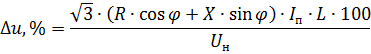
where R and X are the active and reactive resistance of the wire per 1 m length, Ohm / m.
The peak load current is determined based on the number of taps fed by these conductors. For example, with one tap fed from the main wires,

with two taps powered by the same wires,

These formulas show: Ip1 and Ip2 — peak currents, A; In1 — nominal current of the largest motor of the first crane, A; Ip2 — rated current of the second largest motor of the same crane, A; Iп12 — nominal current of the largest motor of the second crane, A; t is the multiple of inrush current.
The most common cross-sections of angle steel contact wires are from 50 X 50 X 5 to 75 X 75 X 10 mm. Angles smaller than No. 5 are not used because of their insufficient rigidity, and above No. 7.5 — because of an increase in mass.
In cases where the desired cross-section of the corner does not pass through the voltage loss, the wires are fed at several points with additional lines. Currently, a special bus is used for recharging, which is most often made of aluminum and is laid on the same fastening structures, parallel to the contact wire.The use of power rods makes it possible to reduce the cross-section of contact wires and significantly reduce capital costs.
Note that in the reference tables the allowable load of AC steel conductors is usually given for a long duty cycle (duty cycle = 100%). At lower duty cycle values, the load can be increased, for example, at duty cycle = 40%, 1.5 times. With direct current, the load on steel trolleys can be increased 1.5-2.0 times compared to the allowable load with alternating current.
The networks supplying the taps, as a rule, are not protected against overload, but only against short circuit. It is recommended under these conditions to select the minimum rated fuse currents for fuses and circuit breakers. In accordance with the rules, the rated current of the fuse must not exceed 3 times the value of the continuous permissible load current of the wires; the tripping current of a circuit breaker with instantaneous release should not exceed the long-term permissible load current of the conductors by more than 4.5 times, and for other designs of machines - by 1.5 times.