Resistances, conductances and equivalent circuits of transformers and autotransformers
 A transformer with two windings can be represented by a T-shaped equivalent circuit (Fig. 1, a), where rt and xt are the active and inductive resistance of the windings, gt is the active conductivity due to active power loss in the transformer steel, bt is the inductive conduction due to the magnetizing current...
The current in the conduction of the transformer is very small (of the order of a few percent of its rated current), therefore, when calculating electrical networks of regional significance, an equivalent circuit with an L-shaped transformer is usually used, in which the conduction is added to the terminals of the primary transformer winding (Fig. 1, b) - to the high voltage winding for step-down transformers and to the low voltage winding for step-up transformers. The use of an L-shaped scheme simplifies the calculations of electrical networks.
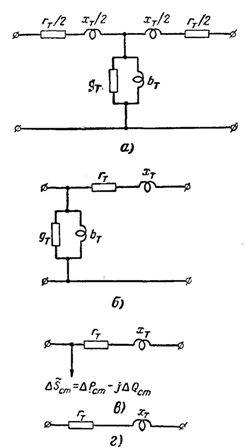
Rice. 1.Equivalent circuits of a transformer with two windings: a-T-shaped circuit; b — G-shaped scheme; c — simplified L-shaped scheme for calculating regional networks; d — a simplified scheme for the calculation of local networks and for the approximate calculation of regional networks.
The calculation is even simpler if the conductivity of the transformer is replaced by a constant load (Fig. 1, c) equal to the no-load power of the transformer:
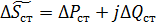
Here ΔPCT — power losses in steel equal to losses during no-load operation of the transformer, and ΔQST — magnetizing power of the transformer equal to:
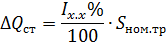
where Ix.x% is the no-load current of the transformer as a percentage of its rated current; Snom.tr — rated power of the transformer.
For local networks n, in approximate calculations of regional networks, only the active and inductive resistance of transformers are usually taken into account (Fig. 1, d).
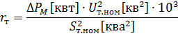
The active resistance of the windings of a two-winding transformer is determined by the known power losses in copper (in the windings) of the transformer ΔPm kW at its rated load:
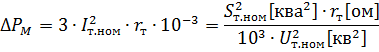
where
In practical calculations, it is assumed that the power losses in copper (in the windings) of a transformer at its rated load are equal to the short-circuit losses at the rated current of the transformer, i.e. ΔPm ≈ ΔPk.
Knowing the short-circuit voltage uk% of the transformer, numerically equal to the voltage drop in its windings at rated load, expressed as a percentage of its rated voltage, i.e.
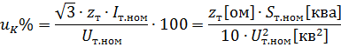
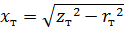
the impedance of the transformer windings can be determined
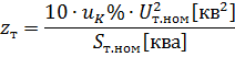
and then the inductive resistance of the transformer windings
For large transformers with very low resistance, the inductive resistance is usually given by the following approximate condition:
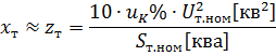
When using the calculation formulas, it should be borne in mind that the resistances of the transformer windings can be determined at the rated voltage of both its primary and secondary windings. In practical calculations, it is more convenient to determine rt and xt at the nominal voltage of the winding for which the calculation is made.
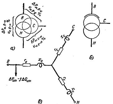
Rice. 2... Transformer circuits with three windings and autotransformers: a — diagram of a transformer with three windings; b — autotransformer circuit; c — equivalent circuit of a transformer with three windings and an autotransformer.
If the transformer winding has an adjustable number of turns, then Ut.nom is taken as the output of the main winding.
Transformers with three windings (Fig. 2, a) and autotransformers (Fig. 2, b) are characterized by the values of power losses ΔРm = ΔРк. and short-circuit voltages ir% for each pair of windings:
ΔPk. c-s, ΔPk. vn, ΔPk. s-n
and
ik.v-s, ℅, ik.v-n, ℅, ik. s-n, ℅,
reduced to the rated power of the transformer or autotransformer. The nominal power of the latter is equal to its passing power. The equivalent circuit of a three-winding transformer or autotransformer is shown in Fig. 2, v.
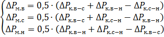
The power losses and the short-circuit voltage relating to the individual rays of an equivalent star of an equivalent circuit are determined by the formulas:
and
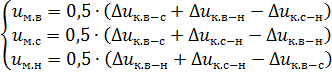
The active and inductive resistance of the rays of the equivalent star of the equivalent circuit are determined from the formulas for two-winding transformers, substituting into them the values of power loss and short-circuit voltage for the corresponding ray of the equivalent star of the equivalent circuit.