Schemes of external (internal quarterly) supply lines
 In order to understand the principles of building diagrams of intra-internal networks, one cannot ignore network diagrams within a quarter, since the selection and construction of the circuit largely depends on the connection between all elements of the network, including the location of the transformer substation, the length and cross-section of the external supply lines.
Feed line or trunk, is called a line designed to transmit electrical energy to several distribution devices or electrical receivers connected to this line at different points.
I'm branching out is called a line extending from the main line to a distribution point (or electrical receiver), or a line extending from a distribution point to an electrical receiver.
The correct selection of the parameters of individual elements of the internal-internal network is possible if the latter are considered in one complex.Here we will consider only the most common power supply schemes for residential buildings, which, as technical and economic calculations show, are optimal and at the same time provide sufficient power supply reliability.
Catering for residential buildings up to five floors
To power residential buildings with a height of up to five floors inclusive, without electric stoves, they use backbone loops with or without a backup jumper... The simplest wiring diagram is shown in fig. 1.
A backup jumper (shown in the figure with a dotted line) is connected in case of failure of one of the supply lines. Thus, all loads are connected to the line which remains in service. Naturally, both supply lines 1 and 2 must be designed both for heating by emergency current and for permissible voltage losses.
It should be borne in mind that PUE allow cables in emergency mode to overload up to 30% within 5 days for a maximum period of no more than 6 hours per day, provided that in normal mode the load on the cables does not exceed 80%. In emergency mode, increased voltage losses (up to 12%) are allowed.
As noted above, electrical receivers of residential buildings without electric stoves with a height of up to five floors, inclusive, belong to the third category of reliability. Therefore, the use of a spare jumper is not mandatory. However, in many large cities, even with a good organization of the repair service, difficulties may arise with the elimination of damage to cable lines within a day. Meanwhile, the cost of a generally rather short cable line, 50–70 m long, is not high, and the convenience of operation is significant.Therefore, in those cities where opening conditions are difficult, the use of spare jumpers is justified.
The disadvantage of the scheme shown in fig. 1, consists in the fact that in the event of a breakdown, for example, on the main line 1, the power supply to the electrical receivers of residential buildings is carried out in a circle, which sometimes leads, even with increased permissible voltage losses in emergency mode, to an increase in the cross-sections of the power cables. The disadvantage of the circuit is that the spare jumper is not used in normal mode.
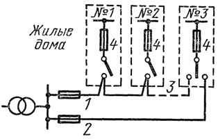
Figure 1. Electrical circuit for power supply of residential buildings up to five floors high (cable network): 1, 2 — power lines, 3 — backup jumper, 4 — input distribution device.
A modification of the described scheme is the scheme shown in fig. 2. If one of the supply lines is damaged, all house users are connected to the line remaining in service, calculated taking into account the permissible overloads in emergency mode, using switches 3.
The diagram in fig. 2 with switches at the inputs is in some cases more economical, since the power supply in emergency mode is provided by one of the lines by the shortest path. Its disadvantage is the complexity of the input device. In addition, four cables with a slightly longer length should be installed in each house, taking into account the "entry" into the house. The scheme is convenient for building a line, with other planning solutions it is less economical.
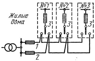
Rice. 2. Power scheme for residential buildings with a height of up to five floors (cable network) with input switches: 1, 2 — power lines, 3 — input-distribution device with a switch.
In small cities, when arranging air inlets for buildings up to five stories inclusive, it is perfectly acceptable to have inlets without reserves, since the damage can be eliminated under these conditions in a few hours.
Catering for residential buildings with a height of 9-16 floors. For houses with 9 — 16 floors, it is used as radial and trunk circuits with switches 3 and 4 at the entrances (Fig. 3). In this case, one of the power lines 1 is used to power the electric receivers of the apartments and the general lighting of the common building premises (basement, stairwells, ceilings, external lighting, etc.). Another power line 2 supplies elevators, fire extinguishers and emergency lighting.
Rice. 3. Power scheme for residential buildings with a height of 9-16 floors: 1, 2 — power lines, 3, 4 — switches.
If one of the power lines fails, all electrical equipment of the house is connected to the line remaining in operation, which is designed for this, taking into account the permissible overloads in emergency mode. In this way, the interruption in the supply of electricity to consumers at home usually lasts no more than 1 hour, that is, the time needed to call an electrician of ZEK and make the necessary switches. The same scheme can be used for buildings up to and including five stories high, equipped with electric stoves.
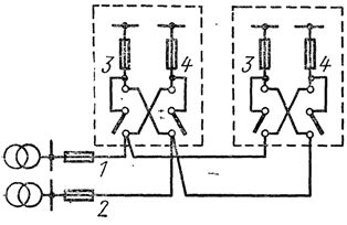
For buildings with electric stoves with a height of 9-10 floors, with elevators, as well as for multi-section gasified buildings with a large number of apartments, the number of supply lines (and inputs) should be increased to three, and sometimes even more. In fig. 4 transmission power circuit for 9-16 story building with three entrances.The first input saves the second, the second the third and finally the third input saves the first.
When supplying buildings according to the diagram in fig. 3 or 4, an important feature of the networks built according to the so-called two-beam circuit with ATS on the low voltage side of the transformer substations, which is as follows. The contactor stations of the PEV series used for the automatic transfer switch are equipped with contactors designed for a continuous current of 630 A. During emergency switching of the supply lines, overloading of the contactors must not be allowed, which can damage the substations and it deprived the connected buildings of electricity.
In such cases, they resort to either connecting the two power lines to one transformer, which, of course, somewhat reduces the reliability of the power supply (for example, when repairing a low-voltage node in transformer substation (TP)) or to the ATS device on the high voltage side. The first method should be considered preferable, since repairs of nodes in city transformer substations are usually planned and residents can be warned in a timely manner, moreover, such repairs are rarely carried out.
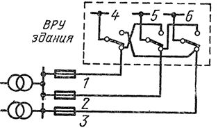
Rice. 4. Scheme of power supply of buildings with a height of 9-16 floors with three inputs: 1, 2, 3 — power lines, 4, 5, 6 — switches.
Catering for residential buildings with a height of 17-30 floors. When determining the power supply scheme for residential buildings with a height of 17 - .30 floors, it should be taken into account that elevators, emergency lighting, obstacles and fire protection devices are electrical receivers of the first reliability category.
For such buildings, radial circuits with ATS are used at power inputs, both emergency lighting and obstacle lights are connected to the latter. From the diagram in fig. 5, it can be seen that when line 2 is damaged, the electrical consumers connected to it are automatically connected through contactors 8, 9 to line 1. When line 1 is damaged, the electrical consumers connected to this line (apartments, work common building lighting) switch to input 6 manually with switch 3.
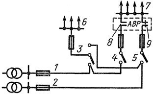
Rice. 5. Electrical circuit of a residential building with a height of 17-30 floors: 1, 2 — power lines, 3 — switch, 4, 5 — breakers, 6 — load (apartments, communal buildings), 7 — elevators, emergency lighting, lights for obstacles, fire fighting devices, 8,9 — main contacts of contactors of the ATS device.
Installation of transformer substations
Speaking of external intra-district networks up to 1000 V (networks from transformer substations to switch clamps of input devices in houses), it is necessary to consider the issue of placing transformer substations. As you know, it is recommended to locate substations providing a residential area approximately in the center of the load. The architectural and planning decisions of the development area do not always allow such an arrangement of substations, which must be taken into account in the design.
In a number of cases, especially in high-rise buildings, the presence of built-in energy-intensive commercial and other enterprises, as well as when installing kitchen electric stoves in buildings, it is economically most justified substations built into buildings... This practice took place in the 50s in Moscow and some other big cities.However, due to the noise from working transformers that penetrated into apartments, especially in panel building structures, built-in substations caused mass complaints from residents and PUE was banned.
Nevertheless, according to the authors, the rejection of built-in substations cannot be justified, because in cases where the integration of substations is economically beneficial, technical solutions can be applied to building structures, excluding the penetration of noise into apartments. An example is the location of the substation on the ground floor, when the residential floors are separated from the substation by a technical floor.
It is possible to build underground substations in close proximity to buildings, which would correspond to modern trends in the construction of large cities. Obviously, special construction measures can be justified (separation of the supporting structures of transformers, additional or thickened ceilings and walls, etc.), as well as the use of transformers with a reduced noise level.
In foreign practice, large residential complexes are equipped with substations located both on floors and in basements and attics. According to experts, such systems allow achieving significant savings of capital investments in the network, reaching in some cases 30-45%, at particularly high load density (electrical heating, air conditioning, etc.). A schematic diagram of the power supply of a building in one of the American cities is shown in fig. 6.
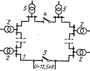
Rice. 6.Schematic diagram of the power supply of a building in one of the cities in the USA: 1 — internal power network with a voltage of 12.5 kV, 2 — 167 kVA power transformers located on the floors of the building, 3, 4 — switching devices, 5 — power transformer of elevators.