Autonomous power sources for enterprises
Interlocking steam turbines (mini-CHP)
 Due to the constant rise in electricity prices, many enterprises that produce and use water vapor for technological needs and heating are switching to independent production of it, using block steam turbine generators with a back pressure turbine for combined production of heat and electricity.
The majority of industrial and production-heating boiler rooms of industrial and municipal enterprises are equipped with steam boilers of saturated or slightly superheated steam for a pressure of 1.4 MPa with a productivity of 10 — 25 t / h.
Using a turbine unit in our own boiler room will allow:
-
significant reduction in the amount of purchased electricity to complete self-sufficiency,
-
reduction of declared power,
-
to fully compensate the reactive power of their electrical installations using the synchronous generator of the turbine unit.
A schematic diagram of a turbine generator (TGU) in a boiler room is shown in fig. 1.
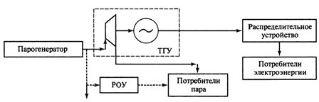
Rice. 1. Scheme of a turbine generator in a boiler room (mini-CHP)
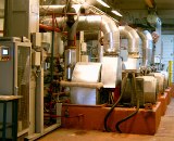
The modular turbine generators installed at the zero level of the boiler room are designed to generate electricity with further use of the steam consumed in the installation for technological and heating needs. Structurally, the units are made in the form of compact power units with 100% factory readiness, consisting of a back pressure turbine, an electric generator and a gearbox, placed together with additional equipment on a common oil tank and placed separate equipment.
Turbine generators include a circulating oil supply system, a local hydrodynamic system for automatic turbine regulation and emergency protection, and a generator control and protection system. Regulator controllers allow manual control and ensure the reception of electrical control signals during remote or automatic control of the device.
Turbine generators are equipped with SG2 type synchronous generators with neutral output power and air cooling.
Turbine generator sets are characterized by:
-
high reliability (period of continuous operation at least 5000 hours),
-
long service life (25 years) and resource (100,000 hours),
-
significant overhaul period (at least 5 years),
-
minimum amount of installation and start-up work,
-
low operating costs,
-
ease of maintenance and undemanding to the level of training of the service personnel,
-
reasonable price with a short (1.5-2 years) payback period,
-
the availability of an after-sales service system.
Gas Turbine Power Plants (GTES)
Unlike the steam turbine (Rankin steam cycle for steam), in gas turbine plant cycles the working fluid is compressed gases heated to a high temperature. As such gases, a mixture of air and products from the combustion of liquid (or gaseous) fuel is most often used.
A schematic diagram of a gas turbine (GTU with heat input at p = const) is shown in Fig. 2.
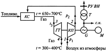
Rice. 2. Schematic diagram of a gas turbine power plant: CS — combustion chamber, CP — compressor, GT — gas turbine, G — generator, T — transformer, M — starting motor, cm — auxiliary needs, RU VN — high voltage switchgear
The air compressor of the gearbox compresses the atmospheric air, increasing the pressure from p1 before p2 and continuously feeds it into the combustion chamber of the burner. The necessary amount of liquid or gaseous fuel is continuously supplied by a special pump. The combustion products formed in the chamber leave it with a temperature t3 and practically the same pressure p2 (if the resistance is not taken into account) as at the outlet of the compressor (p2 = p3). Therefore, fuel combustion (i.e. heat supply) occurs at constant pressure.
In a GT gas turbine, the combustion products adiabatically expand, as a result of which their temperature decreases to t4 (point 4), where T4 = 300 — 400 ° C, and the pressure decreases almost to atmospheric p1. The entire pressure drop p3 — p1 is used to obtain technical work in the LTpr turbine. BigI am part of this work LTo be consumed by driving the compressor. Rvalue LTpr-LTo be spent to produce electricity in the electric generator G or for other purposes.
In order to increase the efficiency of the gas turbine power plant, a method is used to recover the heat of the exhaust gases from the turbine. Unlike the previous schematic diagram (see Fig. 2), it includes a heat exchanger, where the air going from the compressor to the combustion chamber is heated by the exhaust gases leaving the turbine, or the heat of the gases is used in gas heaters for mains boilers for water or waste heat.
Waste heat boiler (KU) for a gas turbine unit (capacity 20 MW) of drum type with forced circulation in the evaporative circuits, arrangement of a tower of heating surfaces with an upper flue gas exhaust can have an open layout or be installed in a building. The boiler has its own frame, which is the main supporting structure for heating surfaces, pipelines, drum and chimney.
The main, backup and emergency fuel for a 20 MW gas turbine is diesel or natural gas. The working load range is 50 - 110% of the nominal.
Modern gas turbine power plants in Russia are based on gas turbines with a capacity of 25 — 100 MW. In recent years, gas turbine power plants with a capacity of 2.5 - 25 MW have become widespread for powering gas and oil fields.
Gas piston power plants
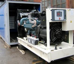
Recently, along with gas turbine power plants, containerized power plants based on gas piston generators using equipment from Caterpillar and others have been widely used.
"Caterpillar" power plants of the G3500 series are autonomous permanent and backup sources of electricity.Gas piston generator sets can be used to generate both electrical and thermal energy by using the heat of a gas engine. In fig. 5.8 shows the energy diagram (energy balance) of the gas piston plant.
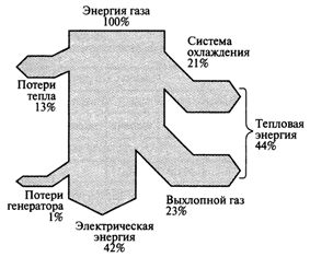
Rice. 3. Energy diagram of a gas piston engine
Such installations with heat recovery can be used in facilities that simultaneously consume heat and electricity, for example, in oil and gas facilities, remote residential and communal services (electricity and heat supply of small villages, etc.), in quarries and mines, in various industrial enterprises.
The main equipment includes: Caterpillar gas engine-generator, heat recovery unit, container, fuel gas supply system, automatic engine oil filling system, electrical equipment and control system.
Diesel power plants
In recent years, diesel power plants with a capacity of 4.5 to 150 MW have become widespread with the use of automated low-speed two-stroke cross-head diesel engines with a turbocharger and electric generators for voltage 6 or 10 kV, alternating current frequency 50 or 60 Hz.
These diesel generators work stably on heavy fuel with a viscosity of up to 700 cG at 50 ° C with a sulfur content of up to 5%, they can also work on any gaseous fuel in dual fuel mode (in a mixture of at least 8% of oil fuel), while the output of electrical energy constitutes about 50% of the energy of the burned fuel, there is an opportunity to increase the efficiency of the installation due to the utilization of the heat of the exhaust gases, they are operated without reducing the efficiency in different climatic conditions, the service life of the units is up to 40 years with a capacity of about 8500 hours per year.