Connection diagrams of capacitor banks for reactive power compensation
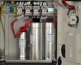 Complete condensing units consist of standard factory cabinets and can be fixed and adjustable.
Regulation can be single-stage or multi-stage. With one-step regulation, the entire device automatically turns on and off. With multi-level regulation, the individual sections of the capacitor banks are switched automatically.
Automatic regulation must guarantee: in the mode of maximum loads of the power system — a certain degree of compensation of the reactive load, in intermediate and minimum load modes — the normal mode of operation of the network (that is, to prevent overcompensation and voltage beyond permissible deviations) .
The first requirement is most easily fulfilled if reactive power (reactive current) is used as the control parameter. Adjusting the power factor cosφ does not provide the most economical network operation mode and is not recommended.
Reactive power compensation using capacitor banks can be individual, group and centralized.
Individual compensation is most often used for voltages up to 660 V. In this case, the capacitor bank is tightly connected to the terminals of the receiver. In this case, the entire network of the power system is unloaded by the reactive power. This type of compensation has a significant drawback — a poor use of the installed capacity of the capacitor bank, since when the receiver is turned off, it turns off and compensating installation.
With group compensation, the capacitor bank is connected to the grid distribution points. At the same time, the use of the installed power increases slightly, but the distribution network from the distribution point to the receiver remains loaded with reactive power of the load.
With centralized compensation, the capacitor bank is connected to the 0.4 kV busbars of the workshop substation or to the 6-10 kV busbars of the main step-down substation. In this case, the transformers of the main step-down substation and the supply network are unloaded from the reactive power. The utilization of the installed capacity of the capacitors is highest.
In order to avoid a significant increase in the cost of disconnection, measurement and other equipment, it is not recommended to install capacitor banks 6-10 kV with a capacity of less than 400 kvar when connecting capacitors using a separate switch (Fig. 1, a ) and less than 100 kvar when connecting capacitors through a common switch with a power transformer, asynchronous motor and other receivers (Fig. 1, b).
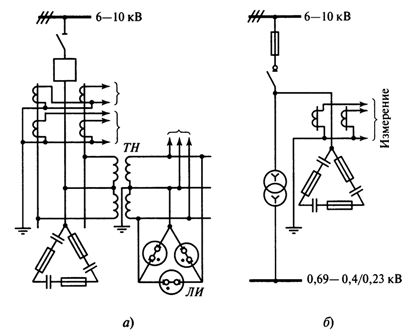
Rice. 1.Circuit diagram of the capacitor banks: a — with a separate switch, b — with a load switch, VT — a voltage transformer used as a discharge resistance for a capacitor, LI — signal indicator lamps
The capacitor installation must have overvoltage protection, which shuts down the battery when the current voltage rises above the permissible value. The installation must be switched off with a delay of 3 - 5 minutes. Restarting is allowed after the network voltage drops to nominal, but not earlier than 5 minutes after its shutdown.
When the capacitors are turned off, it is necessary to discharge the energy stored in them automatically to a permanently connected active resistance (for example, voltage transformer). The value of the resistance should be such that when the capacitors are turned off, an overvoltage occurs at their terminals.
The capacitances of the phases of the capacitor bank must be controlled by stationary current measuring devices in each phase. For installations with a capacity of up to 400 kvar, current measurement is allowed only in one phase. Connecting the capacitors to each other and connecting them to the busbars must be done with flexible jumpers.
Capacitor bank protection
Protection of capacitor banks with a voltage above 1000 V against short circuit can be done by a PC-type fuse or a cut-off relay. Circuit protection? to ground is effected by a current relay T operating through an intermediate trip relay P.
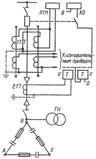
Fig. 2. High voltage capacitor protection circuit
Protection of capacitor banks for single-phase earth faults is established in the following cases: when the earth fault currents are higher than 20 A and when the protection against phase-to-phase faults does not work.
Automatic power control of capacitor banks
The power of the capacitor unit is regulated by:
-
by voltage at the point of connection of capacitors;
-
from the load current of the object;
-
direction of the reactive power in the line connecting the enterprise to the external network;
-
time of day.
The simplest and most acceptable for industrial enterprises is the automatic regulation of the voltage of the substation buses (Fig. 3).
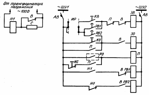
Rice. 3. Scheme of one-stage automatic regulation of the capacitor bank power voltage
Undervoltage relay H1 is used as a trigger for the circuit, which has one marker and one break contact. When the voltage in the substation falls below a predetermined limit, relay H1 is activated and closes its closing contact in the circuit of relay PB1. Relay PB1 with a certain time delay closes its closing contact in the electromagnetic circuit of the EV and turns on the switch.
When the substation bus voltage rises above the limit relay, H1 returns to its original position, opens its NO contact and closes its NC contact in relay circuit PB1. Relay PB2 activates and with a preset time delay turns off the switch — the battery is disconnected. Time relays are used to set the short-term increases and decreases in voltage.
To disconnect the capacitor bank from the protection, an intermediate relay P is provided (protection circuits are usually shown with one closing contact P3).
When the protection is active, relay P is activated and, depending on the position of the switch, turns it off if it is on, or prevents it from turning on for a short circuit by opening the opening contact of relay P.
For multi-stage automatic control of the voltage of several capacitor units, the circuit of each of them is similar, only the starting voltage of the start relay is selected depending on the preset voltage mode of the network.
Automatic regulation of the capacity of the capacitor batteries by the load current is carried out in approximately the same way, only the current relays connected to the network on the supply side (input) serve as a starting body.