Limitations of short-circuit currents in electrical networks of industrial enterprises
 In the power supply systems of industrial enterprises, short circuits (Short circuit), which leads to a sharp increase in currents. Therefore, all the main electrical equipment of the power system must be selected taking into account the action of such currents.
The following types of short circuits are distinguished:
-
three-phase symmetrical short circuit;
-
two-phase — two phases are connected to each other without being connected to the ground;
-
single-phase — one phase is connected to the neutral of the source through the ground;
-
double grounding — two phases are connected to each other and to ground.
The main causes of short circuits are insulation violations of individual parts of electrical installations, incorrect actions of personnel, overlap of insulation due to overvoltages in the system. Short circuits disrupt the power supply of consumers, including undamaged ones, connected to damaged sections of the network, due to a decrease in the voltage on them and an interruption of the power supply.Short circuits must therefore be eliminated with protective devices as soon as possible.
In fig. 1 shows the short-circuit current curve. From the very beginning, a transient process occurs in the power system, characterized by a change in two components of the short-circuit current (SCC): periodic and aperiodic
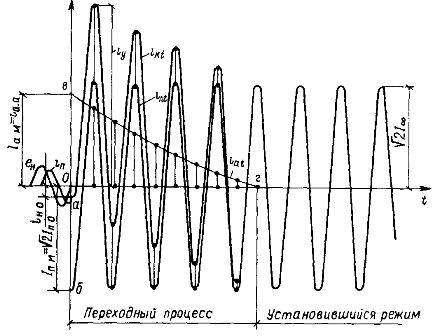
Rice. 1. Short-circuit current change curve
Large industrial plants are usually connected to powerful power systems. In this case, the short-circuit currents can reach very significant values, which leads to difficulties in the selection of electrical equipment according to the conditions of short-circuit stability. Great difficulties also arise in the construction of power supply systems with a large number of powerful electric motors supplying the short-circuit point.
In this regard, when designing power supply systems, it is necessary to determine the optimal short-circuit current... The most common ways of limiting are:
-
separate operation of transformers and power lines;
-
inclusion of additional resistances in the network — reactors;
-
the use of split winding transformers.
The use of reactors is particularly recommended when connecting relatively low-power electrical receivers to the buses of power plants and to high-power substations. When connecting receivers with a shock load — powerful furnaces, valve electric drive — it is often impossible to increase the reactivity of the network by installing reactors, as this leads to an increase in voltage fluctuations and deviations.
In fig. 2 shows a diagram of a 110 kV substation supplying suddenly varying loads.It does not provide for the reaction of the terminals and lines 3 delivering a powerful shock load, so as not to increase the network reactivity and reactive power shocks. In these connections, powerful switches 1 are used. On other lines, responsive and conventional mains switches 2 are provided with a power off of up to 350 — 500 MBA.
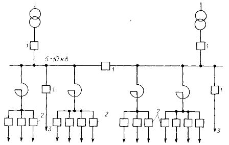
Rice. 2. Scheme of a 110 kV substation that feeds suddenly fluctuating loads: 1 — high-power switches, 2 — medium-power network switches, 3 — lines for supplying consumers with a sharply fluctuating shock load
In modern industrial plants with a branched motor load (concentration plants, etc.) an advanced power supply system with a controlled emergency mode is used to limit short-circuit currents.
In fig. 3 shows the power diagram of the hub. As can be seen from the figure, in the event of a short circuit at point K, the sum of the emergency currents passes through the breaker of the damaged connection (B) — from the mains and the supply from undamaged motors.
In order to limit the short-circuit current flowing through the breaker of the damaged connection, thyristor current limiters of shunt type VS1, VS2 are included for the period of the accident, limiting the component of the short-circuit current from the network. After switching off from switch B, make-ups VS1, VS2 are turned off. The degree of current limiting is regulated by the current limiter R.
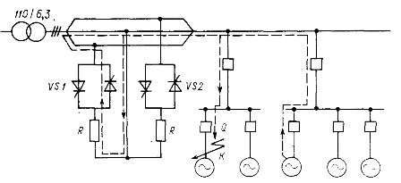
Rice. 3. Power supply scheme with group device for limiting static current
A partial scheme is used for a number of critical mechanisms that do not allow self-starting at rated load and power interruptions parallel operation of transformersshown in fig. 4.
The scheme is a two-section switchgear with twin reactors L1 and L2. In normal mode, switches Q3, Q4 are open and Q5 is closed. The load currents flow on the branches a of the double reactors, and the balancing current on the branches b, which is between the sources, is limited by the resistances of the branches of the double reactors. The scheme allows, in particular, in networks with motor load to maintain a residual voltage, which guarantees the stability of the motors.
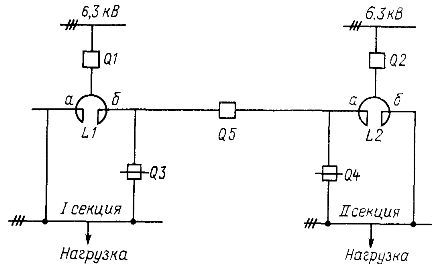
Rice. 4. Scheme with partial parallel operation of the sources
In recent years, complex closed networks of 0.4 kV have begun to be created at industrial facilities, in which parallel operation of workshop transformers TM 1000 — 2500 kVA is carried out.
Such networks provide high quality electrical energy, rational use of transformer power. In fig. 4a shows a diagram in which the limitation of emergency currents during parallel operation of transformers is provided by additional reactors introduced into the 0.4 kV network.
In some cases, the natural removal of transformers allows you to organize the circuit in Fig. 5, but without the use of reactors.
In fig. 5, b shows a complex closed network of 0.4 kV.
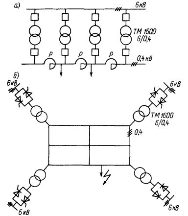
Rice. 5. Schemes with parallel operation of 6 / 0.4 kV workshop transformers: a — with sectional reactors, b — using high-voltage thyristor switches
As can be seen from fig. 5, b, the power transformers are connected to the supply network through thyristor switches, which in emergency mode ensure early shutdown of some of the transformers.In this case, the short-circuit current is limited due to the natural resistances of the complex closed network, which in this case receives power from disconnected transformers.