Design and modes of operation of the urban electrical network
 The city electrical network is a complex of supply networks with a voltage of 110 (35) kV and more, distribution networks with a voltage of 10 (6) — 20 kV, containing transformer substations and lines connecting the central heating station with transformer substations and transformer substations, as well as inputs to consumers and distribution networks with a voltage of 0.38 kV (Fig. 1.).
The specified complex of networks serves to supply utility users (residential buildings, communal institutions), small, medium and sometimes large industrial customers located within the city.
The supply networks with a voltage of 110 (35) kV and higher are built with redundancy on lines and transformers, the power of which, when supplied by overhead lines with a voltage of 110 kV, is 25 MBA, and at 220 kV — 40 MVA. These are the so-called ring patterns that surround the city. Urban network schemes are planned on the basis of the need to ensure an appropriate degree of reliability of power supply to consumers belonging to a certain category.
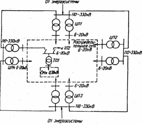
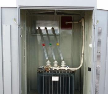
Rice. 1.City power supply system
In the city network for power supply of consumers I categories with a capacity of 10 — 15% of the total capacity of all consumers include: operating and maternity wards of hospitals, boiler rooms of the first category, electric motors of network and feed pumps of boiler rooms of the second category, water supply and sewerage stations, television stations, repeaters, elevators, museums of state importance, central control rooms of the city's electric and heating networks, gas supply networks and outdoor lighting. A special group of Category I electrical receivers includes government buildings and institutions.
To electric receivers II categories, the capacity of which is 40-50% of the total capacity of all users of the city network includes residential buildings with electric cooking receivers with more than 8 apartments, residential buildings with 6 or more floors, dormitories, educational institutions.
See also: Power schemes for users of category II
The capacity of electricity consumers of category III is 30-50% of the total capacity of consumers in the city network. These include all electrical receivers that do not belong to category I and II electrical receivers.
Power lines with a voltage of up to 20 kV of the city network in construction areas with buildings of 4 floors and more are carried out by cable (with aluminum conductors, with lead, aluminum, plastic or rubber sealed sheaths and armor of steel strips) and are laid in earth trenches, blocks (with a significant probability of mechanical damage), channels and tunnels (when the lines exit the processor).
In the areas where the city is built up, levers on 3 floors and under power lines with a voltage of up to 20 kV are built by air. No more than 3 sections with different cross-sections are allowed on one distribution line. The cross-sectional area of the cable line must be at least 35 mm2. Power cable lines are usually laid in different routes or in different trenches.
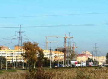
Overhead power lines with a voltage of up to 20 kV are built with pin insulators on wooden (with reinforced concrete attachments) or reinforced concrete supports with steel-aluminum wires with an area of up to 70 mm2 located horizontally and along a triangle. On a line with a voltage of up to 1 kV, the neutral wire is located under the phase wires, and the wires for outdoor lighting are under the neutral wire.
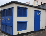
Transformer substations and distribution points are mainly built as free-standing, enclosed type with internal mounting equipment. These constructions are distinguished by significant volumes of the construction part (up to 324 m3). They are also used embedded in buildings, attached to buildings and underground TP and RP. In areas with overhead networks, there are mast transformer substations.
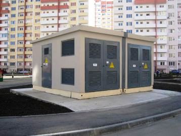
TP or RP buildings can be brick, block, panel. In addition, complete transformer substations are used for both indoor and outdoor installation, providing for overhead or cable line connection and consisting of a transformer and 0.38 kV switchgear.
A network with a voltage of 6 — 20 kV operates with an isolated or compensated neutral, which leads to the need to choose insulation for network voltage.In the presence of compensation for capacitive earth fault currents, cable networks can operate for a long time in single phase to earth fault mode. See here for more details: The use of electrical networks with an isolated neutral
When choosing the parameters of equipment (switches) for distribution networks, it is necessary to take into account that the short-circuit power in a city network with a voltage of 6 and 10 kV on 6-10 kV buses of the processor should not exceed 200 and 350 MBA, respectively . This is due to the need to ensure the thermal resistance of the cable lines.
Features of the city network mode of operation include:
-
pronounced load peaks in the daily load schedule, which leads to an uneven load on network equipment during the day and year;
-
low power factor of energy consumers with a tendency to further decrease;
-
continuous growth of electricity consumption.
Decision-making in the selection of the parameters of the urban electrical network in the process of its design, as well as in the connection of new connections to the operated network, is based on knowledge of the calculated loads of individual elements of the power supply system.
Calculation of the load consists of determining its value at the input of each user and then finding the load of an individual network element. Consumers of electric energy in the city network are conditionally divided into residential buildings and communal services. The load of industrial enterprises connected to the city grid is taken according to their power supply projects or according to actual measurements.
In order to develop science-based projects for the development of the electricity network, it is necessary to forecast electricity consumption for a period of more than 10 years. Short-term and operational forecasts (from a few hours to the season) are made for the operational management of the network.
Load management, in order to reduce electricity consumption during peak load hours and ensure the balance of active power, as well as the most economical operation of power plants, is reduced to equalizing the daily load schedule at the expense of consumers (increasing load at night and decreases during peak load hours). The most effective means of encouraging consumers to work at night is a lower electricity tariff during certain hours.