Cable lines and transformer substations in urban distribution networks
The city's electrical system can be roughly divided into two parts. The first includes power supply networks-electrical networks and step-down substations with a voltage of 35-220 kV, intended for the distribution of electrical energy between the districts of the city.
They are powered by local power plants or the regional power grid. The 6-10 kV busbars of the step-down substation are the central power supply (CPU) of the city's power grids. The distribution of electrical energy from a central processor or RP between transformer substations (TS) is carried out, as a rule, through distribution networks of 6-10 kV.
Currently, in cities, cable networks almost completely replace aerial networks, despite the higher cost, since then the streets of cities and the territory of enterprises are not cluttered with electric wires and supports.
Currently, power cables are used for lines with voltages up to 220 kV, but at voltages of 35 kV and higher, the advantage remains for overhead lines due to the structural difficulties associated with the production of power cables for such high voltages.
Urban distribution networks of 6-10 kV and 380/220 V, as a rule, are implemented only by cable. Exceptions are low-rise and individual built-up areas (cottages and horticultural associations).
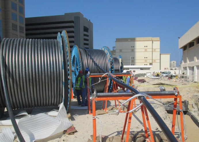
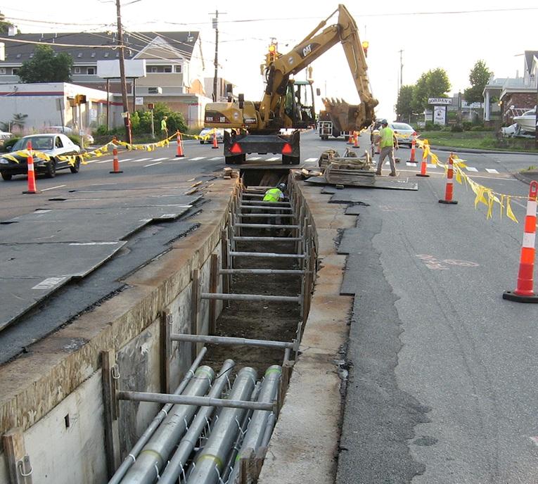
Cable lines are laid in the ground along the impassable part of the streets (under sidewalks, lawns, etc.). Single cables in microdistricts are laid in trenches or in blocks of reinforced concrete panels, asbestos-cement or ceramic pipes. Cables with metal sheaths and structures on which the cables are laid must be grounded. When laying cables in the ground, the depth of the trench should be at least 0.7 m, the distance between adjacent cables at least 100 mm, from the edge of the trench to the outermost cable — at least 50 mm.
On streets and squares saturated with underground communications and with more than 10 cables, it is recommended to place them in collectors and cable tunnels. Cutting and connecting cables are practically no different from industrial ones.
The brands of power cables and their area of application in urban networks are given in a table. 1.
Table 1. Cables used in urban electrical networks
Cable brand Characteristics of the cable sheath Laying method
Lead sheathed cables with impregnated paper insulation
SGT, ASGT Without external coating In pipes, tunnels, ducts SB, ASB Armored with steel strip with protective cover On the ground SP, ASP Armored with flat steel wires with protective cover In the ground if there are significant tensile forces SK, ASK Armored with large galvanized steel wires with protective cover Under the water
Aluminum sheathed cables impregnated with paper
AG, AAH No cover In tunnels, canals AB, AAB Armored with steel belts with protective cover On the ground ABG, AABG Armored without cover Indoors in canals, in tunnels
Cables with rubber insulation
SRG, ASRG Lead jackets without protective coating Indoors in ducts, in tunnels VRG, AVRG PVC jacket without cover Indoors in ducts, in tunnels NRG, ANRG Non-flammable rubber jacket without cover Indoors in ducts, in tunnels SRB, ASRB With lead jacket , armored with a steel strip with a protective cover On the ground
Fireproof cables with low smoke and gas emissions
VBbShvng-LS, AVBbShvng-LS Insulation of polyvinyl chloride composition with reduced fire hazard, shell and protective coating of polyvinyl chloride composition In cable structures and premises, incl. fire hazard
XLPE insulated cables
PvP, APvP XLPE insulation, PE sheath On ground PVV, APvV XLPE insulation, PVC plastic sheath In cable structures and premises, in dry soils PvVng-LS, APvVng-LS Cover made of low fire hazard PVC compound Same but with laying on the ground
Cables with plastic insulation, with plastic sheath
VVB, AVVB PVC insulation, armored with steel tape, with protective cover On the ground VPB, AVPB PVC insulation, armored with steel tape, with protective cover On the ground
Hose cables
ASH, AASHV Aluminum sheath with outer PVC hose cover Indoors, in ditches, in soft soil
The main brands of bare wires that are used in overhead lines of urban electrical networks:
-
A — from seven or more aluminum wires of the same diameter, twisted in concentric layers (section 16-500 mm2);
-
AKP — the same, but the interwire space is filled with grease with increased heat resistance;
-
AC-steel-aluminum wire (section 16-500 mm2);
-
PITA - the same, but with grease.
Currently, overhead lines with a voltage of up to 10 kV are recommended to be used self-supporting insulated conductors (SIP)… The self-supporting insulated conductor for overhead lines up to 1 kV is a structure in which insulated phase conductors are twisted around the neutral carrier cable, as well as, if necessary, a conductor for street lighting.
The design parameters of overhead lines of urban electrical networks are given in a table. 2.
Table 2. General dimensions of overhead lines of urban electrical networks
dimensions
Minimum permissible distances, m, at mains voltage up to 1 kV 6-10 kV 35 kV The height of the wire above the pavement or the roadway 6 7 7 Height of the branches to the entrance of the building: — above the roadway 6 7 7 — outside the roadway 3.5 4.5 5 Distance from the outermost wire to the building in a populated place 1 ( for a blank wall) 2 4 1.5 (for windows or balconies)
Distribution substations (PP) with a voltage of 6-10 kV are made in the form of independent buildings with complete one-way service switchgear of the KSO type.
Modern transformer substations (TP) in cities are implemented as complete units using unified block diagrams. They differ in the number of installed transformers, purpose and switching schemes.
The most widespread are modular complete transformer substations (BKTPu) for internal maintenance and complete transformer substations for external installation (KTPN) and external services.
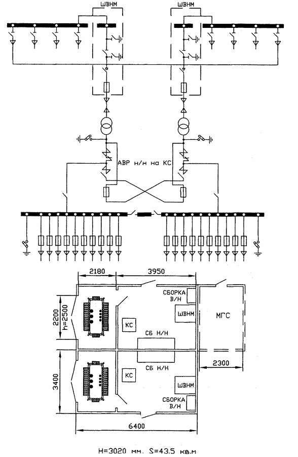
Scheme of the transformer substation BKTPu-630
Substation BKTPu is a finished product, fully equipped with equipment, except for power transformers, which are installed after the installation of the substation on the foundation. It is possible to install power transformers of local and foreign production, both oil-cast and dry-cast.
A substation of this type can be equipped with transformers with a capacity of up to 1000 kVA (for example, of the TMG type). The RU-10 kV is designed as a hermetically sealed single-sided service switchgear with SF6 insulation. RU-0.4 kV is also complete, of the ShchO-59 type, with PN-2 fuses and circuit breakers for rated currents of 250, 600 and 1000 A.
The automatic transfer switch (ATS) when installing transformers with a capacity of up to 630 kVA is carried out on contactors, and when installing 1000 kVA transformers - on circuit breakers.
If necessary, the 0.4 kV switchgear provides for the installation of a special panel for powering the street lighting network. The lighting panel has two bus systems and two contactors, which allows changing the lighting mode depending on the time of day (evening and night) by switching the power supply from one bus system to another.
In areas of low-rise buildings, KTPN single-transformer substations in a monoblock overall design with transformers with a capacity of 63-400 kVA can be used to supply electrical and lighting loads of industrial, urban and rural networks.
The KTP cabinet is divided into three compartments by solid metal partitions. The compartment with transformer and high-voltage fuses and the RU-0.4 kV compartment are located on the lower level, and the RU-10 (6) kV cabinet is on the upper level.
The design of the transformer substation implies the use of high and low voltage air and cable seals. The substation is installed on a rammed and leveled platform or on a foundation. KTP with air inlet is connected to the line through a disconnector, which is installed on the nearest support.
On the main sections of cable lines of residential and public buildings, input distribution units (ASU) are installed, which are the final elements of the city's electrical network. This is where the line of balance between utilities and consumers usually falls.
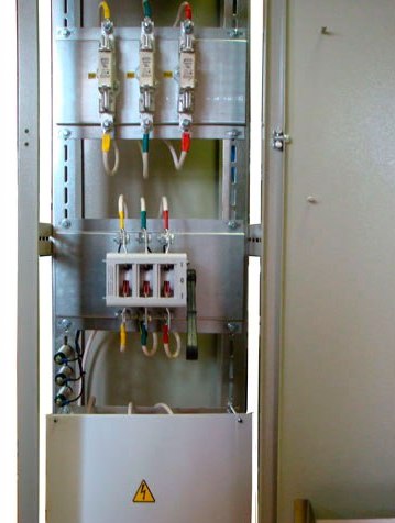
The input devices are equipped with fuses and other switching devices, which makes it possible to provide reliable protection of city electrical networks from damage caused by malfunctions of consumers, and the possibility of disconnecting consumers during repairs and preventive tests.
With the introduction in 1980 of GOST 19734-80 "Input and distribution devices for residential and public buildings", all ASUs were made unified and completed by standard panels.
As an example, consider the UVR-8503. The series includes 8 types of input and 62 types of distribution boards, which allows them to be used in a set for all types of residential and public buildings with different numbers of supply and output lines. In the composition of the input panel 2VR-1-25 for powering consumers II-III categories include the following elements: a three-pole switch and fuse type PN-2 in each phase, an AE-1031 automatic machine lighting lamp and a capacitor for the interference suppression system.