Modern technologies for reactive power compensation
For the rational use of electricity, it is necessary to provide economical methods for its production, transmission and distribution with minimal losses. To do this, it is necessary to exclude from the electrical networks all factors leading to the occurrence of losses. One of them is the phase lag of the flowing current from the voltage in the presence of an inductive load, since loads in industrial and household power transmission networks usually have an active-inductive nature.
Purpose of systems reactive power compensation consists in compensating the total phase shift by introducing a phase advance. This leads to a reduction of the current flowing through the networks and, accordingly, to a reduction of parasitic active losses in the wires and the distribution network. The necessary headway is created by connecting capacitors in parallel with the supply network. For maximum efficiency, the trigger circuit should be connected as close as possible to the inductive load.
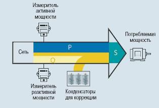
Power factor correction systems reduce the reactive component of the current flowing through the power network. When the nature of the load changes, it is necessary to reconfigure the correction circuits accordingly. For this, automatic correction systems are usually used, which perform stepwise connection or disconnection of individual correction capacitors. Image schematically showing the principle of the appearance of reactive components in networks.
Power Factor Correction Benefits:
-
The payback period is from 8 to 24 months due to the reduction in the price of electricity. Corrections reduce the reactive power in the system. Electricity consumption is reduced and its price is reduced proportionally.
-
Effective use of networks. A high power factor means more efficient use of distribution networks (more net power flows for the same total power).
-
Stabilizing voltage.
-
Less voltage drop.
-
By reducing the current flowing, the side cross section of the cable… Alternatively, in existing systems, additional power can be transmitted over a cable of constant cross-section.
-
Reduction of losses in electricity transmission. Transmission and switching devices operate with a lower value of current. Accordingly, ohmic losses also decrease.

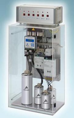
Key components of reactive power compensation systems
Power factor correction capacitors provide the necessary phase advance for the current flowing, which compensates for the phase lag in circuits with inductive loads.The capacitors for the power factor correction circuits must withstand the large inrush currents (> 100 IR) that occur when switching capacitors. When the capacitors are connected in parallel in the battery, the inrush currents become even higher (> 150 IR), because the inrush current flows not only from the supply circuits, but also from the capacitors connected in parallel.
EPCOS AG manufactures capacitors with voltages from 230 to 800V and power from 0.25 to 100kVAr. They offer dry or oil-filled capacitors depending on the operating conditions.
The main differences between the capacitors of this manufacturer are:
-wide operating range -40 ... + 55 ° C (-40 ... + 70 ° C for MKV series capacitors);
— withstand starting currents up to 200 * In of the nominal (up to 300 * In for the PhaseCap compact series and up to 500 * In for the MKV series);
-service life of capacitors from 100,000 h to 300,000 h (at temperature class -40 / D according to IEC 60831-1);
— for the PhaseCap compact and MKV series, the permissible number of operations is 10,000 per year and 20,000, respectively;
— the overpressure switch is activated in all 3 phases, completely eliminating the possibility of a potential shock to the condenser housing;
— operation is permitted up to 4000 m above sea level.
— of course, the technology of self-healing, cutting waves, etc. are present
Controllers
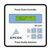 Modern power factor correction controllers are based on microprocessors. The microprocessor analyzes the signal from the current transformer and gives commands to control the capacitor banks by connecting or disconnecting individual capacitors or entire banks.The intelligent management of the correction capacitors allows not only to ensure the maximum full load of the capacitor banks, but also to minimize the number of switching operations and thus to optimize the life of the capacitor bank.
In the product line of the company EPCOS AG there are 4x, 6 (7m), 12 (13) step controllers for controlling both electromechanical and thyristor contactors. There are also combined versions capable of switching both types of contactors simultaneously. At the customer's request, the controllers are equipped with an interface for connecting to a computer or an AMR system.
The main differences between the controllers of this manufacturer are:
-text-digital menu in Russian;
— the liquid crystal display works well at low temperatures;
— there is a backlight on the display;
— fixing and storing the main parameters that affect the service life of the capacitors (overvoltage, temperature rise, harmonics of current and voltage up to 19 inclusive, the number of starts and the time of operation of each stage)
— there are functions for protection and shutdown of the compensation system when parameters are exceeded, which affect the life of capacitors and many others
Simplified and cheaper models are also available for use in simpler systems.
Switching devices
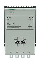 Electromechanical or thyristor contactors are used to switch capacitors in standard rectification systems or capacitors and chokes in detuned systems. Inclusion in power circuits is done either with the help of mechanical contacts or by using semiconductor devices.Electronic switching is preferred, especially when fast switching is required in dynamic correction systems. For example, if the main load in the electrical network is welding machines.
Electromechanical contactors manufactured by EPCOS AG are available in capacities up to 100 kvar. Thyristor contactors today have the widest range: 10 kvar, 25 kvar, 50 kvar, 100 kvar, 200 kvar for 400V and 50 kvar and 200kvar for operation in 690V networks.
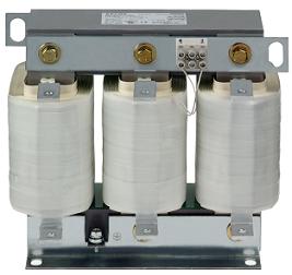
Throttles
Distribution networks often have harmonic distortions caused by the use of modern electronic devices that create a non-linear load. Such devices can be, for example, controlled electric drives, uninterruptible power supplies, electronic ballasts, welding machines, etc. Harmonics can be dangerous for capacitors in rectifier circuits, especially if the capacitors operate at a resonant frequency. Including a choke in series with a correction capacitor allows you to somewhat tune the resonant frequency in the system and avoid possible damage to it.
The 5th and 7th harmonics are particularly critical (250 and 350 Hz in a 50 Hz network). Deranged capacitor steps reduce harmonic distortion in power circuits.
The choke range from EPCOS AG has capacities from 10 to 200 kvar.
Accessories
The EPCOS AG product line also includes accessories for building reactive power correction systems according to special requirements:
— protective caps and housings to increase the degree of protection of the capacitors to IP64;
— discharge chokes, allowing to make the speed of the reactive power correction system about 1 second without reducing the service life of capacitors and special discharge resistors and chokes for systems with thyristor contactors;
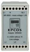
— devices that allow, unlike the summing transformer, to control a system of 4 correction systems at once;
— adapters for connecting the controller to mains voltage
The main 13 factors in building a concealer
 This is worth paying attention to when designing or choosing the right installation for yourself:
1. Determine the required rms power (kvar) of the capacitor for power factor correction.
2. Design the capacitor bank in such a way as to provide the switching step capacity within 15 … 20% of the required power. It is not necessary to ensure that capacitors are switched in 5% or 10% increments, as this will only result in a high switching frequency, but will not appreciably affect the power factor value.
3. Try to design a capacitor bank with standard resolution values, preferably multiples of 25 kvar.
4. Do not forget to observe the minimum allowable distances between the capacitors (20 mm) and protect them with screens or a sufficient distance from heating by other elements of the system.
5. The temperature in the installation area of capacitors should not exceed 35? C. Otherwise, their service life will be reduced.
Remember that prolonged heating of a capacitor by only 7 ° C above the norm reduces its service life by 2 times!
6.Measure the harmonic currents in the power cable without correction capacitor and at different loads. Determine the frequency and maximum amplitude of each of the harmonics present. Calculate the total harmonic distortion of the current: THD-I = 100 · SQR · [(I3) 2 + (I5) 2 + … + (IR) 2] / I1
7. Calculate the individual coefficients of each of the harmonics: THD-IR = 100 IR / I1
8. Measure the presence of harmonics in the supply voltage outside the system. If possible, measure them on the high voltage side. Calculate the total harmonic distortion of the voltage: THD-V = 100 · SQR · [(V3) 2 + (V5) 2 + … + (VN) 2] / V1
9. Harmonic level (measured without capacitor) above or below THD-I> 10% or THD-V> 3%.
If YES, use a set filter and go to step 7.
If NO, use a standard concealer and skip steps 10, 11 and 12.
10. Level of 3rd current harmonic I3> 0.2 · I5
If YES, use a filter with p = 14% and skip step 8.
If NO, use a filter with p = 7% or 5.67% and go to step 8.
11. If THD -V = 3 … 7% — you need a filter with p = 7%
> 7% — a filter with p = 5.67% is required
> 10% — special filter design required. Please contact the representative office of EPCOS AG in Russia and the CIS countries.
Do not skimp on chokes in the presence of harmonics in the electrical network! As practice shows, this «economy» will lead to the failure of capacitors within 6-10 months! Replacing capacitors, taking into account the cost of installation, will cost the same money that will go to the initial installation of chokes!
12.Select the appropriate components using the tables developed by EPCOS (or the assistance of the company representative) for the adjusted filter correctors and the standard values for effective power, line voltage, frequency and a predetermined p-factor.
Always use only genuine EPCOS components designed to build corrected filter power factors. Please note that chokes are specified for their effective power for the selected supply voltage and frequency. This power is the effective power of the LC circuit at the fundamental frequency.
The voltage rating of the detuned filter capacitors must be higher than the supply voltage, as series connection of the inductor will cause overvoltage. Capacitor contactors are specially designed for reliable operation with capacitive loads and must provide a reduced starting current.
13. Fuses or automatic electromagnetic fuses can be used as short circuit protection devices. Fuses do not protect capacitors from overload. They are only for short circuit protection. The tripping current of the fuse must exceed the nominal current of the capacitor by 1.6 ... 1.8 times.