The use of capacitors to compensate for the reactive power of household loads
Among the numerous factors affecting the efficiency of the power supply system (SES), one of the priority places is occupied by reactive power compensation problem (KRM). However, in utility user distribution networks containing mostly single-phase, individually switched load, KRM devices are still underutilized.
It was previously believed that due to the relatively short feeders of urban low-voltage distribution networks, the small (kVA units) connected power and the spreading of the loads, the PFC problem did not exist for them.
For example, in chapter 5.2 [1] it is written: «for residential and public buildings no reactive load compensation is provided.» If we take into account that in the last decade the consumption of electricity per 1 m2 of the residential sector has tripled, the average statistical capacity of power transformers of urban municipal networks has reached 325 kVA, and the area of use of transformer power has shifted upwards and is in within 250 … 400 kVA [2], then this statement is questionable.
The processing of the load graphs made at the entrance of a residential building shows: during the day the average value of the power factor (cosj) varies from 0.88 to 0.97, and phase by phase from 0.84 to 0.99. Accordingly, the total consumption of reactive power (RM) varies from 9 ... 14 kVAr, and phase by phase from 1 to 6 kVAr.
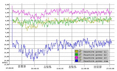
Figure 1 shows the daily RM consumption graph at the entrance of a residential building. Another example: the registered daily (June 10, 2007) consumption of active and reactive electricity in the TP of the urban grid of Sizran (STR-RA = 400 kVA, electricity consumers are mostly single-phase) amounts to 1666.46 kWh and 740.17 kvarh (weighted average value cosj = 0.91 — dispersion from 0.65 to 0.97) even with the correspondingly low load factor of the transformer — 32% during peak hours and 11% during minimum measurement hours.
Thus, given the high density (kVA / km2) of the utility load, the constant presence of a reactive component in the energy flows of the SES, leads to significant losses of electricity in the distribution networks of large cities and the need to compensate them through additional sources of generation.
The complexity of solving this problem is largely due to the uneven consumption of RM in individual phases (Fig. 1), which makes it difficult to use traditional for industrial networks KRM installations based on three-phase capacitor banks controlled by a regulator installed in one of the phases of the compensated network.
The experience of our foreign colleagues is of interest in increasing the power reserve of urban thermal power plants. In particular, the developments of the electricity distribution company Edeinor S.A.A. (Peru) (it is part of the Endesa group (Spain), which specializes in the production, transmission and distribution of electricity in a number of South American countries), according to KRM in low-voltage distribution networks at a minimum distance from consumers [3]. On order from Edeinor S.A.A., one of the largest manufacturers of low-voltage cosine capacitors-EPCOS AG launched a series of single-phase capacitors HomeCap [4], suitable for small utility loads.
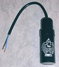 The nominal capacity of the HomeCap capacitors (Fig. 2) varies from 5 to 33 μF, which makes it possible to compensate the inductive component of the PM from 0.25 to 1.66 kVAr (at a mains voltage of 50 Hz in the range of 127. . . 380 V ).
The reinforced polypropylene film is used as a dielectric, the electrodes are made by spraying metal — MKR technology (Metallised Polypropylene Kunststoff). The winding of the section is standard round, the inner volume is filled with a non-toxic polyurethane compound. Like all cosine capacitors from EPCOS AG, the HomeCap capacitors have the property of «self-healing» in case of local destruction of the plates.
The cylindrical aluminum housing of the capacitors is insulated with a heat-shrinkable polyvinyl tube (Fig. 2), and the terminals of the double electrode blades are covered with a dielectric plastic cap (protection degree IP53), thus guaranteeing complete safety during operation in domestic environment confirmed by the relevant certificate of standard UL 810 (US safety laboratories).
The built-in device, which is activated when the excess pressure inside the jacket is exceeded, automatically shuts down the condenser in case of overheating or avalanche collapse of the section. The diameter of the HomeCap capacitors is 42.5 ± 1 mm, and the height, depending on the value of the nominal capacity, is 70 ... 125 mm. Vertical extension of the condenser housing, in the case of protection against excess internal pressure, not more than 13 mm.
The capacitor is connected with a two-core flexible cable with a cross-section of 1.5 mm2 and a length of 300 or 500 mm [4]. Permissible heating of cable insulation — 105 ° C.
The operation of HomeCap capacitors is possible indoors at an ambient temperature of -25 … + 55 ° C. Deviation of the nominal capacity: -5 / + 10%. Active power losses do not exceed 5 watts per kvar. Guaranteed service life of up to 100,000 hours.
Fastening the HomeCap capacitors to the mounting surface is done with a clamp or bolt (M8x10) connected to the bottom.
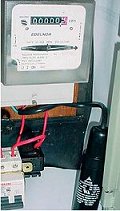 In fig. 3. shows the installation of the HomeCap condenser in the metering box. The capacitor (in the lower right corner) is connected to the terminals of the electricity meter
HomeCap capacitors are manufactured in full compliance with the requirements of IEC 60831-1 / 2 [4].
According to Edeinor SAA, [3] the installation of HomeCap capacitors with a total capacity of 37,000 kvar in 114,000 households in the Infantas district of northern Lima increased the weighted average power factor of the distribution network from 0.84 to 0.93, saving approximately 280 kWh per year .for each connected kVAr RM or a total of about 19,300 MWh per year. In addition, taking into account the qualitative changes in the nature of the household load (switching of the power supply of electrical appliances, active ballasts of energy-saving lamps), distortion of the sinusoidality of the mains voltage, at the same time with the help of HomeCap capacitors, it was possible to reduce the level of harmonic components — THDU averaged by 1%.
In contrast to urban ones, the need for RPC for rural low-voltage distribution networks has never been questioned [5] because of the active energy consumption for RM transmission over an extended open (tree-like) high-voltage line (OHL ) with the voltage of 6 (10) kV is the highest [6]. At the same time, the insufficient ratio of KRM funds to the connected capacity of electrical receivers is explained by purely economic reasons. Therefore, for the SPP of rural utility and household and small (up to 140 kW) industrial users, the question of choosing the cheapest version of KRM is a priority.
One of the technical difficulties in the practical implementation of the recommendation of 80% of RPC directly in the rural low-voltage networks [5] is the lack of capacitors suitable for installation of overhead lines.According to the calculations, the average value of the residual (not allowing overcompensation) RM during transmission over HV 0.4 kV with an active power of 50 kW for a mixed, with a predominance (more than 40%) of the utility load is 8 kvar , therefore, the optimal nominal RM of such capacitors should be within a few tens of kvar.
Consider the KRM system used on the overhead lines of low-voltage networks in Jaipur (Rajasthan, India) by the power company Jaipur Vidyut Vitran Nigam Ltd based on the PoleCap® series capacitors (Fig. 4) manufactured by EPCOS AG [7] . The monitoring of the SPP, containing about 1000 MVA with an installed capacity of 4600 transformers 11 / 0.433 kV with a single power of 25-500 kVA, showed: the summer load of the transformers was 506 MVA (430 MW), the winter — 353 MVA ( 300 MW); weighted average cosj — 0.85; total losses (2005) — 17% of the volume of electricity supply.
In the course of the KRM pilot project, 13375 PoleCap capacitors were installed in the connection nodes to low voltage transformers, directly on the supports of 0.4 kV overhead lines, with a total RM of 70 MVAr. Including: 13000 5 kvar capacitors; 250 — 10 kvar; 125 — 20 sq. m. As a result, the value of cosj increases to 0.95, and losses decrease to 13% [7].
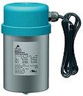 These capacitors (Fig. 4 and Fig. 5) are a modification of a well-proven type of metal-film capacitors made according to the MKR / MKK (Metalized Kunststoff Kompakt) technology [8] - simultaneously increasing the area and increasing the electrical strength of the layer contact metallization of the electrodes, due to a combination of flat and wavy cut of the edges of the film, laid with a small displacement of the bends, characteristic of the MKR technology.In addition, the PoleCap series includes a number of three-phase capacitors PM 0.5 ... 5 kVAr, made according to the traditional MKR technology [8].
Improvements to the basic design of series MCC capacitors made it possible to directly (without an additional case) install PoleCap capacitors outdoors, in damp or dusty rooms. The condenser body is made of 99.5% aluminum and is filled with an inert gas.
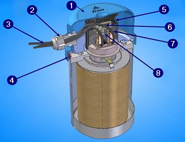
Figure 5 shows:
-
resistant plastic cover (item 1);
-
hermetically sealed, surrounded by a plastic ring (pos. 5) and filled with epoxy compound (pos. 7), the terminal block version (pos. 8) provides the degree of protection IP54.
The connection (Fig. 5) is made by sealing a cable seal (position 2) from three single-core 2-meter cables (position 3) and a ceramic module of discharge resistors (position 6) by crimping and soldering the contact connections.
For the convenience visual control overpressure protection is triggered, a bright red band appears on the extended part of the condenser housing (position 4).
The maximum permissible difference in ambient temperature is -40 ... + 55 ° C [8].
It should be noted that since the KRM capacitors must be protected against short-circuit currents (PUE Ch.5), it seems advisable to build fuses inside the housing of the HomeCap and PoleCap capacitors which are triggered by the section breakdown.
KRM's experience in utility networks in developing countries with a high level of network losses shows that even simple technical solutions — the use of unregulated batteries of special types of cosine capacitors — can be economically very effective.
Author of the article: A.Shishkin
Literature
1. Instructions for the design of urban electrical networks RD 34.20.185-94. Approved by: Ministry of Fuels and Energy of the Russian Federation on 07.07.94, RAO «UES of Russia» on 05.31.94. Entered into force on 01.01.95.
2. Ovchinnikov A. Losses of electricity in distribution networks 0.4 ... 6 (10) kV // News of electrical engineering. 2003. No. 1 (19).
3. Correction of the power factor in the electrical networks of Peru // EPCOS COMPONENTS #1. 2006
4. HomeCap capacitors for power factor correction.
5. Guidelines for the selection of means of voltage regulation and reactive power compensation in the design of agricultural equipment and electrical networks for agricultural purposes. M.: Selenergoproekt. 1978
6. Shishkin S.A. Reactive power of consumers and network losses of electricity // Energy saving No. 4. 2004.
7. Jungwirth P. On-site power factor correction // EPCOS COMPONENTS No. 4. 2005
8. PoleCap PFC capacitors for external low voltage PFC applications. Published by EPCOS AG. 03/2005. Order no. EPC: 26015-7600.