High voltage fuses PKT, PKN, PVT in rural distribution networks
In rural electrical installations, fuses of the PKT and HTP types (previously known as PK and PSN, respectively) are used for this voltage.
Device and principle of operation of PKT type fuses
PKT fuses (with quartz sand) are produced for voltages 6 ... 35 kV and rated currents 40 ... 400 A. The most common are PKT-10 fuses for 10 kV, installed on the high voltage side of rural transformer substations 10 / 0.38 kV. The fuse holder (Fig. 1) consists of a porcelain tube 3 filled with quartz sand, which is reinforced with brass caps 2 with caps 1. The fusible links are made of silver copper wire. At a rated current of up to 7.5 A, they are used several parallel inserts 5 wound on a ribbed ceramic core (Fig. 1, a). At high currents, several spiral inserts are installed (Fig. 1).
Rice. 1.Holders for PKT type fuses: a — for nominal currents up to 7.5 A; b — for nominal currents 10 … 400 A; 1 — cover; 2 — brass cap; 3 — porcelain tube; 4 — quartz sand; 5 — fusible links; 6 — work indicator; 7 — spring
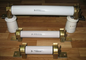
Rice. 2. PKT type fuse: 1- base; 2- supporting insulator; 3- contact; 4- cartridge; 5- lock
This design provides good arc damping as the inserts are of considerable length and small cross-section. The metallurgical effect is used to lower the melting point of the insert.
To reduce overvoltages that can occur during rapid arc extinction in narrow channels (slots) between quartz grains, fuses with different sections along the length are used. This provides an artificial tightening of the arcing.
The fuse holder is sealed — after filling the tube with quartz sand, the caps 1 covering the openings are carefully sealed. Therefore, the PKT fuse works silently.
The operation of the fuse is determined by the pointer 6, which is usually held by a special steel insert in the retracted position. In this case, the spring 7. is also kept in a compressed state. When the fuse is triggered, the steel insert burns out after the working one, because all the current begins to pass through it. As a result, the pointer 6 is thrown out of the tube by the released spring 7.
In fig. 2 shows the assembled fuse PKT. On the base (metal frame) 1 there are two supporting insulators 2. The fuse holder 4 is inserted with brass caps into the spring holders (contact device) 3 and tightened with a lock. The latter is provided to keep the cartridge in the holders when the emergence of electrodynamic forces during the flow of large short-circuit currents. They manufacture fuses for both indoor and outdoor mounting as well as special reinforced fuses with increased breaking breaking strength.
Construction and principle of operation of fuses type PKN
PKN (formerly PKT) type fuses are manufactured to protect measuring voltage transformers. Unlike the PKT fuses in question, they have a constantan with a fuse wound on a ceramic core. This insert has a higher resistance. Thanks to this and the small cross-section of the insert, a current-limiting effect is provided.
PKNU fuses can be installed in a network with very high short-circuit power (1000 MV × A), and the breaking capacity of reinforced PKNU fuses is not limited at all. PKN fuses are smaller compared to PKT and are not equipped with an operation indicator (the fuse can be judged by the readings of the devices connected to the secondary side of the voltage transformers).
Construction and principle of operation of blown fuses, type PVT
Fuses of the PVT type (discharge, the former name — ignition type PSN) are produced for voltage 10 ... 110 kV. They are intended for installation in open switchgear. In rural electrical networks, the most widely used fuses are PVT-35 for the protection of transformers with a voltage of 35/10 kV.
Rice. 3. PVT type fuses: a, b — general view and fuse holder PVT (PSN) -35; c — fuse HTP (PS) -35 MU1; 1 and 1′-pin knife; 2 — axis; 3 — supporting insulator; 4 — fusible link; 5 — tube made of gas-generating dielectric; 6 — flexible communication; 7 — peak; 8 — branch pipe
The main element of the fuse holder is a gas-generating tube 5 made of vinyl plastic (Fig. 1.5). Inside the tube there is a flexible wire 6, connected at one end to a fusible insert 4 inserted into the metal head of the cartridge, and at the other end to the contact tip 7.
The fuse holder is located on two support insulators 3 mounted on the base (frame). The chuck head is gripped by a special holder on the upper insulator. Fixed on the lower insulator is a knife 1 for contact with a spiral spring, which tends to rotate the knife about the axis 2 to position 1 '. The knife 1 is engaged with the contact tip 7 of the cartridge. Zinc fusible links are used, as well as double inserts of copper and steel (a steel insert, located parallel to the copper one, perceives the force of a spring trying to pull the flexible wire out of the cartridge; in the case of a short circuit, the copper insert first melts, then this the steel insert).
After burning the fusible link, the contact knife is released and, rotating (tilted) under the action of the spring, pulls the flexible wire, which is then ejected from the cartridge.
Under the action of the arc formed after melting the insert, the walls of the vinyl plastic tube vigorously release gas. The pressure in the cartridge rises, the gas flow creates a strong longitudinal explosion, extinguishing the arc. The process of ejecting hot gases through the lower opening of the cartridge is accompanied by a sound similar to a shot. Due to the increase in arc length when the flexible connection is released, no surges occur during the tripping process, but these fuses also have no current-limiting effect.As can be seen from Figure 1.5, the fusible link is not located in the pipe, but in a metal cap that covers one end. This eliminates gassing during normal operation when the fuse can also heat up to a high temperature.
The industry produces a discharge (ignition) fuse of the type PVT-35MU1, shown in fig. 5, c. The cartridge of this fuse, unlike the one discussed above, has a metal tube 8, in which a copper valve is installed, which closes the transverse hole of the tube. When extinguishing large short-circuit currents, when the arc develops intensively, the pressure in the cartridge quickly increases and ejects the valve, as a result of which the tap hole opens. When extinguishing an arc with low currents, the nozzle opening remains closed, providing an increase in pressure in the cartridge.
Controlled fuses, type UPS-35
In order to eliminate one of the significant disadvantages of fuses - the difficulty of matching devices installed in series due to the spread of characteristics - on the basis of fuses PVT (PS) -35MU1, controllable fuses UPS -35U1 designed to protect transformers with a voltage of 35/6 have been developed … 10 kV. There are also developments of 110 kV fuses.
The flexible wire inside the controlled fuse holder is not rigidly connected to the fuse, but through a contact system that provides mechanical interruption of the fuse circuit under the action of the actuator when the relay protection is actuated.
When a short circuit occurs, the relay protection is activated, and as a result of the action of the drive, the contact knife, together with the flexible link, moves down.In this case, the contact system located inside the cartridge opens. The remaining processes — further movement and disposal of the flexible wire, arc extinguishing — are carried out in the same way as in the case of a blown fuse in an uncontrolled exhaust gas fuse. At high short-circuit currents, the fuse of the controlled fuse blows before the relay protection trips.
A controlled fuse option without a fuse is also possible. This excludes additional heating of the fuse, you can increase the rated and interrupted current.