Automatic reconnection of lines in rural distribution networks
Short circuits occurring in the elements of the power system can be both stable and unstable. In any case, such an element is disabled by relay protection and power supply users are disconnected for the time required to restore. Automatic Reclose (AR) is designed to quickly restore power to consumers in the event of unstable short circuits and therefore reduce or prevent damage to consumers.
Intermittent short circuits on overhead lines in rural areas can be caused by thunderstorms, wind causing wires to collide, short circuits in branches, birds, and other random causes. The number of unstable short circuits is 60-90% of the total number of interruptions due to protection, and those caused by lightning - about 60% of all unstable short circuits.
After disconnecting the damaged element through relay protection, the cause of the unstable short circuit is self-destructive.Therefore, energizing the line or transformer by the automatic recloser restores normal operation of the supply circuit. The effectiveness of automatic reclosing of rural 10 kV lines is particularly high because they are very long, pass through postcards of the area and, as a result, are often exposed to weathering.
Statistics show that automatic reclosers for overhead lines of all voltages annually average 60-75% of successful actions. Due to the high efficiency of the automatic closing devices PUE require automatic reclosing for all overhead and mixed (cable-overhead) lines of all types with a voltage above 1000 V.
Single double-acting automatic closing devices are used, it is especially important to install them in unmanned substations, in sections. The time delay (pause without current) to close the tripped circuit breaker should be at least 2 s in the first cycle and at least 15-20 s in the second cycle.
Research conducted at MIISP showed the effectiveness of using one-time automatic reclosing for 10 kV networks with a delay of 15 — 20 s.
Single-shot automatic closing devices have 40-50% of successful actions, double-50-60%, and the latter are recommended to be installed on unregulated lines.
Basic requirements for automatic closing devices:
-
Automatic reclosing shall be performed when the circuit breaker is tripped by relay protection, except for the operation of relay protection immediately after the rapid closing of the circuit breaker;
- Automatic reclosing shall not occur during operational tripping of the remote circuit breaker or remote control;
- Automatic reclosing should be done with a pre-selected time delay;
-
Automatic closing must be done with a given frequency;
-
the auto-closer must have an auto-return to be ready for a new action.
At present, a typical AC single-acting regenerator circuit is still very widely used, where the principle of reclosing the automatic reclosing from the mismatch of the breaker position when it is tripped by the "off" protection and the control key position is used "included".
For automatic reclosing of 10 kV power lines, the industry produces a single-action reclosing relay of type RPV-58, double-action-RPV-258 and for substations with alternating current using power supplies of type RPV-358.
APV-2P Semiconductor Automatic Recloser
The APV-2P solid state automatic recloser (or relay) is designed for double automatic reclosing of 6-35 kV circuit breakers working together with direct and indirect acting drives and can be mounted on the relay panel of outdoor switchgear cabinets devices (KRUN) and internal installation (KRU).
The relay is made in the form of a single unit; the power is supplied from a single-phase source of alternating voltage with a frequency of 50 Hz, with a nominal value of 100 and 220 V with a deviation of 0.85 to 1.1 of the nominal value.
The device provides adjustment of the delay from 0.6-1 to 5-7 s for the first cycle of automatic closing and from 1.2-2 to 20-28 s for the second cycle of automatic closing, without taking into account the preparation time of the drive for "on" operation. It is possible to increase the delay time of the second automatic reclosing cycle to 40 s.
The time to prepare the APV-2P relay for re-operation is not less than 10 and not more than 60 s.
The device does not work when the circuit breaker is immediately turned off by personnel, contains elements of operability without turning it off, and it is also possible to disable the first and second cycles of automatic switching on and the relay as a whole.
Relay setting items are displayed on the front panel.
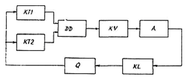
The electrical diagram of a functional switch relay is shown in Fig., which contains two timing elements KT1 and KT2, logical element «OR» DD, threshold element KV, amplifier A, actuator KL. The input and output of the relay is connected to the auxiliary contacts of the Q switch (motorized switch).
In the initial state, that is, when the switch Q is turned on, no signal is received at the input elements KT1 and KT2 of the relay, and there is also no signal at the output of the relay (element KL).
When the switch Q of the power line is turned off, for example, when the relay protection is triggered, its contact closes and the two time elements KT1 and KT2 of the relay start, that is, the time of their operation begins.

Electrical functional diagram of the APV-2P device
After the set time of the first automatic reclosing cycle has elapsed, the time element KT1 is triggered.The output signal of the time element KT1 through the logic element «OR» DD, the threshold element KV is fed to amplifier A. The amplified signal from the output of element A is fed to the actuator (output relay) KL, when triggered, the signal is fed to the coil (electromagnet) to turn on the switch. The latter turns on the power line again, since the automatic reclosing of the circuit breaker takes place after the time of the first cycle has expired.
In the case of repeated disconnection of the power line by the switch Q, that is, the failed first cycle of automatic reclosing,. after the drive is prepared for the "on" operation, the timing of the second auto-close cycle begins, while only the KT2 time element is started, since the KT1 time element does not have time to prepare for restart. After the set time of the second AR cycle has elapsed, the timer KT2 is activated and provides operation of the output element KL, which again acts on the closing solenoid of the Q switch.
If the second AR cycle fails, switch Q turns off, but timers KT1 and KT2 do not start because switch Q is in the on state for insufficient time to prepare them to start.
If the first or second automatic reclosing cycle is successful and the time to prepare timers KT1 and KT2 for starting has elapsed, the relay is again ready to act on the switch to turn it on.
The APV-2P device is serially produced by the experimental plants in Riga «Energoavtomatika».
Single automatic recloser APV-0.38
The device for automatic reclosing of 0.38 kV lines is intended for installation in KTP 10 / 0.4 kV, equipped with automatic air switches of the A3700 series with electromagnetic drive.
Studies of emergency interruptions of 0.38 kV lines in rural areas show that unstable faults occur in these networks due to lightning surges, overlapping wires in strong winds, touching them with tree branches when entering buildings. It should be noted that the interruption of 0.38 kV lines also occurs due to overloading in case of improper operation of protective devices of electrical receivers. In these cases, when the line comes back on, power will be restored to consumers.
It has been found that when the circuit breaker is re-energized or the fuse is replaced at a 10 / 0.4 kV transformer substation, power is restored to consumers in 50-60% of all outages.
The APV-0.38 device operates on the automatic machine (type A3700), which is triggered at high emergency currents (phase-phase and single-phase short circuit, overload), which does not reduce the existing level of electrical safety.
Thus, the APV-0.38 device is designed to increase the reliability of power supply to consumers in rural areas and, accordingly, reduce damage due to electricity shortages. It is designed as an attachment to a solid state circuit breaker and an electromechanical relay and can be used in all industries with long 0.38 kV overhead distribution lines.
The device is triggered on all emergency circuit breaker trips; during operational shutdowns the device does not work.
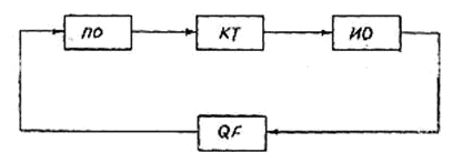
The functional diagram of the APV-0.38 device is shown in the figure.

Functional diagram of the device APV-0.38. PO — launch body; CT — time delay organ; IO — executive body; QF — circuit breaker
Currently, some improvements have been made in this automatic reclosing device, which allows avoiding the dependence of the reclosing operation on the ambient temperature and voltage level and other factors.
