Constructive design of workshop electrical networks
Depending on the adopted power supply scheme and environmental conditions, workshop electrical networks perform buses, cable lines and wires.
Bus applications
Spines work open, protected or closed rails.
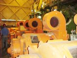
Open busbars are used, as a rule, for highways to which electricity receivers are not directly connected. They are made with aluminum busbars fixed on insulators and laid along the trusses and columns of the workshop at an inaccessible height.
 Feeding electrical distribution points (RP) from open busbars, they are made with a cable or wire laid in pipes. A similar design of the network is characteristic of foundries and rolling shops of metallurgical plants, welding shops of mechanical assembly plants, forging and pressing shops.
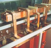
A protected bus is an open bus channel, protected from accidental contact with the tires and penetration of foreign objects on them by means of a mesh or a box of perforated sheets. These days, factory-made closed tires are widely used.Such a busbar is called complete because it is supplied in the form of individual prefabricated sections, which are three or four busbars enclosed in a sheath and secured by the sheath itself or by insulators-ticks.
For making straight sections of lines, straight sections are used, for bends - corner sections, for branches - triple and transverse, for branches - branch sections, for connections - connecting sections, for compensating changes in length with temperature extensions - compensating and for length adjustment — adjustment of such. The connection of the sections at the place of their installation is carried out with a pile, bolts or plugs.
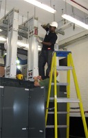
Complete bus ducts of the ShMA73UZ, ShMA73UZ and ShMA68-NUZ types are produced for the main highways. When local conditions do not prevent this, the rails are fixed at a height of 3 — 4 m above the floor of the room on brackets or special racks. This provides a short length of descents to the distribution network, power distribution points or powerful electricity receivers.
 Distribution lines Made with full busbars of the ShRA73UZ and ShRM73UZ series. Individual receivers are connected to the SHRA through junction boxes with cable or wire laid in pipes, boxes or metal hoses.
Each 3-meter SHRA section has eight junction boxes (four on each side) with circuit breakers or fuses with circuit breakers. For connecting junction boxes, windows with automatically closing covers are provided on the busbar sections. This ensures a safe connection of the boxes to the bus, which is energized during operation. When you open the box cover, the power to the receiver is cut off.
Connecting the ShRA to the busbar is done by cable jumpering the input box of the ShRA with the junction part of the ShMA. The SHRA inlet box can be installed at the end of a section or at the junction of two sections.
Fastening of bus channels of the SHRA type is carried out on racks at a height of 1.5 m above the floor, with brackets to the walls and columns, on cables to the trusses of the building.
A network of stores made with full rails:
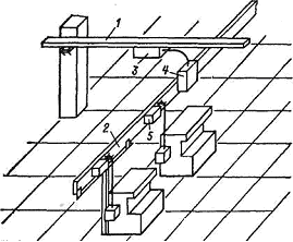
1 — main conduit, 2 — distribution conduit, 3 — splitter of the main cables, 4 — input box, 5 branch box
The use of cables in service electrical networks
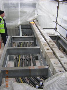
Cables are mainly used in radial networks to supply powerful concentrated loads or load nodes. At laying cables in buildings they are placed in an open manner on walls, columns, trusses and ceilings, in pipes laid in the floor and ceilings, ducts and blocks.
Open laying of cables inside buildings is carried out with armored and more often unarmoured cables without an outer coating of jute-bitumen (from the fire-hazardous conditions). The cable route should be as straight as possible and away from different pipes. If a cable is laid on the walls and ceilings, it is fixed with clamps. When laying several cables, factory supporting structures are used, assembled from separate parts - racks and shelves.
The most common in industrial premises is laying cables in special channels if a large number of cables are laid in one direction. In this case, a channel of reinforced concrete or bricks is built into the floor of the workshop, which is covered with reinforced concrete slabs or corrugated steel sheets.Cables inside the channel are laid on standard prefabricated structures mounted on the side walls.
The advantages of such cable laying are in their protection from mechanical damage, ease of inspection and revision during operation, and the disadvantages are in significant capital costs.
Laying of armored cables in ducts acceptable in rooms with any nature of the environment. However, if water, reactive liquids or molten metal can enter the channels, such a seal is not allowed.
Blocks and tunnels are used for laying particularly critical cable lines with a large number of cables running in one direction, in rooms with an aggressive environment and with possible spills of metal or flammable liquids. Cables in tunnels and blocks are laid on standard metal structures.
Cable tunnels are well protected from mechanical damage, cables are easy to check and repair. Significant disadvantages, however, are the significant capital costs for the construction part and the worse cooling conditions.
 Electrical wiring in pipes are reliable and at the same time the most time-consuming and expensive. Therefore, it is recommended to avoid laying cables (wires) in pipes. In the absence of such an opportunity (for example, due to the limited dimensions of some sections of the track, the need to protect the electrical wiring from mechanical damage, in rooms with an explosive atmosphere, etc., it should be used widely combined laying of cables (wires) : in tubes on some sections of the route and open on others.
Application of wires in workshops electrical networks
Working networks made of wires are laid openly on insulating supports, in steel and plastic pipes.
Open routing of insulated wires is allowed in all rooms, except for rooms with an explosive atmosphere.
Laying networks with insulated wires in ordinary steel pipes is allowed only in hazardous areas. Lung steel pipes can be used in all environments and outdoor installations, but they are recommended in humid, especially humid rooms, with chemically active environments and for outdoor installations. Thin-walled electric welded pipes are not used in rooms with explosive, humid, especially humid , chemically active environment, in external installations and in the ground; they are recommended for use in other environments, including fire hazard areas.
 The use of plastic pipes saves electrical wiring. Plastic pipes for electrical wiring used from vinyl plastic, polyethylene and polypropylene. Vinyl plastic pipes are rigid, they are used for hidden and open seals in all environments, except explosive and fire-hazardous, and for seals in hot workshops. When laid open, vinyl plastic pipes are not allowed to be used in hospitals, children's facilities, on ceilings and in livestock buildings.
Application of polyethylene and polypropylene pipes prohibited in explosive and fire-hazardous premises, in buildings below the second degree of fire resistance, in entertainment, children's and medical facilities, in residential and public administrative institutions, in high-rise buildings.
Polyethylene and polypropylene pipes are recommended for hidden laying in dry, wet, dusty and chemically aggressive environments.
Plastic pipes with hidden wiring in fireproof walls and ceilings are laid in grooves, fixing them every 0.5 — 0.8 m with alabaster mortar; in walls and ceilings made of combustible materials, strips of asbestos sheet with a thickness of at least 3 mm are placed under the pipes.
In a number of industries (in particular in tools) to supply low-power users located in rows, they use modular networks laid in the floor.
Such a network consists of main pipes laid in the floor and floor junction boxes, above which branching columns are installed to supply the receivers with alternating current up to 60 A at a voltage of up to 380 A. Boxes for modular networks of the KM- 20M type have a dustproof design. Structurally, the boxes have four openings with branch pipes in the side walls — two for the main line and two for the branches. Distribution boxes are most often located at a distance of 2 — 3 m. The power supply is carried out with single-core uncut wires. The lines coming from the columns to the electrical receivers are done with cables or wires in flexible metal hoses or pipes.