Converter devices in power systems
 Electrical energy is generated in power plants and distributed mainly in the form of alternating current with a supply frequency. A large number though electricity consumers in industry requires other types of electricity for its power supply.
Most often required:
- D.C. (electrochemical and electrolysis baths, direct current electric drive, electric transport and lifting devices, electric welding devices);
- alternating current non-industrial frequency (induction heating, variable speed AC drive).
In this connection, it becomes necessary to transform alternating current to direct (rectified) current or when converting alternating current of one frequency to alternating current of another frequency. In electrical power transmission systems, in a thyristor DC drive, there is a need to convert direct current to alternating current (current inversion) at the point of consumption.
These examples do not cover all cases where conversion of electrical energy from one type to another is required.More than a third of all electricity produced is converted into another type of energy, which is why technical progress is largely related to the successful development of conversion devices (converting equipment).
Classification of technology conversion devices
The main types of converting devices
The share of converting technological devices in the energy balance of the country occupies a significant place. Advantages of semiconductor converters, compared to other types of converters, are undeniable. The main advantages are the following:
— Semiconductor converters have high regulation and energy characteristics;
— have small dimensions and weight;
— simple and reliable in operation;
— provide contactless switching of currents in power supply circuits.
Thanks to these advantages, semiconductor converters are widely used: non-ferrous metallurgy, chemical industry, railway and urban transport, ferrous metallurgy, mechanical engineering, energy and other industries.
We will give definitions of the main types of conversion devices.
 Rectifier It is a device for converting AC voltage into DC voltage (U ~ → U =).
An inverter is called a device for converting direct voltage into alternating voltage (U = → U ~).
A frequency converter serves to convert an alternating voltage of one frequency into an alternating voltage of another frequency (Uf1→Uf2).
An AC voltage converter (regulator) is designed to change (regulate) the voltage supplied to the load, i.e. converts AC voltage of one quantity to AC voltage of another quantity (U1 ~ → U2 ~).
Here are the most widely used types of technology conversion devices... There are a number of conversion devices designed to convert (regulate) the magnitude of direct current, the number of converter phases, the shape of the voltage curve, etc.
Brief characteristics of the element base converting devices
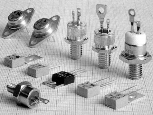
All converting devices, designed for different purposes, have a common principle of operation, which is based on the periodic switching on and off of electric valves. Currently, semiconductor devices are used as electrical valves. The most widely used diodes, thyristors, triacs and power transistorsworks in key mode.
1. Diodes Represent two-electrode elements of an electric circuit with one-sided conductivity. The conductance of a diode depends on the polarity of the applied voltage. Generally, diodes are divided into low-power diodes (allowable average current Ia ≤ 1A), medium-power diodes (adding Ia = 1 — 10A) and high-power diodes (adding Ia ≥ 10A). According to their purpose, diodes are divided into low-frequency (fadd ≤ 500 Hz) and high-frequency (fdop> 500 Hz).
 The main parameters of the rectifier diodes are the highest average rectified current, Ia addition, A, and the highest reverse voltage, Ubmax, B, which can be applied to the diode for a long time without danger of disturbing its operation.
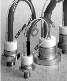
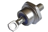
In medium and high power converters Apply powerful (avalanche) diodes. These diodes have some specific characteristics as they operate at high currents and high reverse voltages, resulting in significant power release in the p-n junction.So effective cooling methods should be provided here.
Another feature of power diodes is the need to protect against short-term overvoltages arising from sudden load drops, switching and emergency modes.
 The protection of the power supply diode from overvoltage consists in the transfer of a possible electrical breakdown p-n — a transition from surface areas to bulk. In this case, the breakdown has an avalanche character, and the diodes are called avalanche. Such diodes are able to pass a sufficiently large reverse current without overheating local areas.
When developing circuits of converter devices, it may be necessary to obtain a rectified current exceeding the maximum allowable value of a single diode. In this case, the parallel connection of diodes of the same type is used with the adoption of measures to equalize the constant currents of the devices included in the group. To increase the total allowable reverse voltage, series connection of diodes is used. At the same time, measures are provided to exclude the uneven distribution of the reverse voltage.
The main characteristic of semiconductor diodes is the current-voltage (VAC) characteristic. The semiconductor structure and diode symbol are shown in Fig. 1, a, b. The reverse branch of the current-voltage characteristic of the diode is shown in Fig. 1, c (curve 1 — I — V characteristic of an avalanche diode, curve 2 — I — V characteristic of a conventional diode).
Rice. 1 — Symbol and inverse branch of the diode current-voltage characteristic.
Thyristors It is a four-layer semiconductor device with two stable states: a state of low conductivity (thyristor closed) and high conductivity (thyristor open). The transition from one stable state to another is due to the action of external factors. Most often, to unlock a thyristor, it is affected by voltage (current) or light (photothyristors).
 Distinguish diode thyristors (dynistors) and triode thyristors control electrode. The latter are divided into single-level and two-level.
In single-action thyristors, only the thyristor turn-off operation is performed on the gate circuit. The thyristor goes into the open state with a positive anode voltage and the presence of a control pulse on the control electrode. Therefore, the main distinguishing feature of the thyristor is the possibility of arbitrary delay at the time of its firing in the presence of a forward voltage on it. The locking of a single-operation thyristor (as well as a dinistor) is carried out by changing the polarity of the anode-cathode voltage.
 Dual duty thyristors allow the control circuit to both unlock and lock the thyristor. Locking is performed by applying a control pulse of reverse polarity to the control electrode.
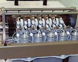
It should be noted that the industry produces single-action thyristors for permissible currents of thousands of amperes and permissible voltages of a unit of kilovolts. Existing double-action thyristors have significantly lower allowable currents than single-action ones (units and tens of amperes) and lower allowable voltages. Such thyristors are used in relay equipment and in low-power converter devices.
In fig.2 shows the conventional designation of the thyristor, the schematic of the semiconductor structure and the current-voltage characteristic of the thyristor. The letters A, K, UE respectively denote the outputs of the anode, cathode and thyristor control element.
The main parameters that determine the choice of a thyristor and its operation in the converter circuit are: allowable forward current, Ia additive, A; allowable forward voltage in the closed state, Ua max, V, allowable reverse voltage, Ubmax, V.
The maximum forward voltage of the thyristor, taking into account the operating capabilities of the converter circuit, should not exceed the recommended operating voltage.
Rice. 2 — Thyristor symbol, semiconductor structure diagram and thyristor current-voltage characteristic
An important parameter is the holding current of the thyristor in the open state, Isp, A, is the minimum forward current, at lower values of which the thyristor turns off; parameter needed to calculate the minimum permissible load of the converter.
Other types of conversion devices
Triacs (symmetrical thyristors) conduct current in both directions. The semiconductor structure of a triac contains five semiconductor layers and has a more complex configuration than the thyristor. Using a combination of p- and n-layers create a semiconductor structure in which, at different voltage polarities, the conditions corresponding to the direct branch of the current-voltage characteristic of the thyristor are fulfilled.
Bipolar transistorsworks in key mode.Unlike the bi-operational thyristor in the main circuit of the transistor, it is necessary to maintain a control signal throughout the entire conducting state of the switch. A fully controllable switch can be realized with a bipolar transistor.
Ph.D. Kolyada L.I.