Types of electrical network configuration
 The variety of work efforts of various sites (including military) determines the variety of their power schemes. It is customary to distinguish two main directions of development of power supply schemes:
1. Classic, which develops mainly in those areas where the increase in the load of consumers is expected only or develops simultaneously with the construction of power transmission networks.
2. Forced when the electrical networks are already built and designed for a certain load and categorization, but later there is a need either to increase the capacity of the network, or to build new taps from the existing network, or even to change their configuration.
Such networks, as a rule, bear the names of simple closed or complex closed configurations of electrical networks.
Consumer power supply schemes depend on the remoteness of energy sources, the general power supply scheme of a given area, the territorial location of consumers and their capacity, requirements for reliability, survivability, etc.
It is very difficult to choose the type and configuration of the network. they must meet the conditions of reliability, economy, ease of use, safety and development possibilities.
The configuration of the network is determined by the mutual arrangement of the line elements, and the type of network depends on this user categories and the extent of their reliability and survivability.
Consumers of the 1st category must be supplied with electricity from two independent power sources on two separate lines. They allow for power interruption during the automatic activation of the backup power source.
For category 2 consumers, in most cases, the power supply is also provided on two separate lines or on a line with two circuits. Since the emergency repair of overhead lines is of short duration, the rules allow the supply of electricity to consumers of category 2 and one line.
For category 3 users, one line is sufficient. Non-redundant and redundant schemes are used in this regard.
It is not superfluous — there are no spare lines and transformers. They include radial circuits (Fig. 1., a), power consumers of 3 categories (sometimes 2 categories). Backup circuits supply consumers of categories 1 and 2. They include a ring (Fig. 1., b), with two-sided power supply (Fig. 1., d) and complexly closed with nodal points I, II, III, IV (Fig. 1 ., e).
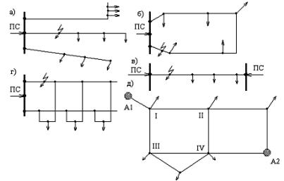
Rice. 1. Power grid configurations: Substation — substation; A1 and A2 — power units (stations or substations) a) — radial configuration; b) — ring configuration; c-single-circuit c) double-sided power supply; d) — two-circuit trunk configuration; e) — complex closed configuration.
In some cases, the construction of lines in redundant lines is carried out in two stages. One line is built and only when the load increases to the design level, the second is built. Mixed wiring configurations—redundant along with non-redundant—can also be used.
Graphically, electrical networks are presented in the form of schematic diagrams, on which all elements are depicted with conventional symbols, connected to each other in the same sequence as in reality.
Schematic diagrams of electrical networks are usually drawn in the most visual form, so that all electrical circuits can be easily traced. At the same time, the relative position of TP and RP on the diagram, the shape and length of the power line may not correspond to the scale and the real their location on the ground, and the switching devices, meters and protective equipment of these circuits may be missing.
In fig. 2. shows an approximate diagram of the electrical network. In it, overhead transmission lines 1 ... 3 with a voltage of 110 kV with transformer substations 1 ... 4 connect power plants ES1 and ES2 to each other and to energy centers TsP1 and TsP2. The remaining overhead and cable lines with a voltage of 35 kV and below, connected to the power stations, distribute the electricity between the facilities.
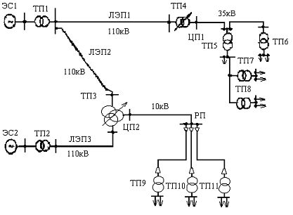
Fig. 2. Diagram of the electrical network
Symbols are used on electrical network schematic diagrams.
Individual sections of the electrical network, in which the transmission and distribution of electrical energy are carried out at the same voltage, are depicted in the form of simplified diagrams.On them, the beginning of the network on the side of the power source is indicated by a circle, the electrical receivers — by arrows suggesting the direction of energy transfer, and the distribution points — by nodal points (Fig. 3.).
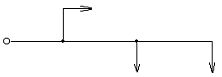
Rice. 3. Design scheme of the electricity section
In the plans, individual elements of the electrical network are indicated according to GOST 2. 754-72.
Typical power supply schemes for industrial plants
I. I. Meshteryakov