Spare circuits for transformers in the calculation of electrical networks
 By the nature of the tasks to be solved, the calculations of electrical networks are divided into two parts:
1. Calculations of network modes. These are calculations of voltages at nodal points, currents and powers in lines and transformers at certain intervals.
2. Parameter selection calculations. These are calculations of the selection of voltages, line parameters, transformers, compensating and other devices.
To make the above calculations, you must first know the equivalent circuits, resistance and conductance of power lines and transformers.
In the calculations of electrical networks, taking transformers into account, instead of the T-shaped equivalent circuit known from the course of electrical engineering, the simplest L-shaped equivalent circuit is usually used, which greatly simplifies the calculations and does not cause significant errors. Such an equivalent circuit is shown in Fig. 1.
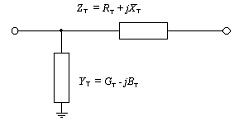
Rice. 1. L-shaped transformer equivalent circuit
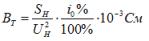
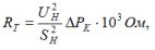
The main parameters of the equivalent circuit of one phase of the transformer are the active resistance RT, reactivity HT, active conductance GT and reactive conductance BT. The reactive conductance of VT is inductive in nature. These parameters are missing from the reference literature. They are determined experimentally according to passport data: no-load losses ∆PX, short-circuit losses DRK, short-circuit voltage UK% and no-load current i0%.
For transformers with three windings or autotransformers, the equivalent circuit is presented in a slightly different form (Fig. 2).
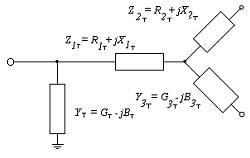
Rice. 2. Equivalent circuit of a transformer with three windings
In the passport data of transformers with three windings, the short-circuit voltage is indicated for three possible combinations: UK1-2%-short-circuited on the medium voltage (MV) winding and the supply side of the high voltage (HV) winding; UK1-3% — in case of short-circuiting of the low-voltage winding (LV) and power supply from the HV winding; UK2-3% — in case of short-circuiting of the LV coil and the supply on the HV side.
In addition, versions of the transformer are possible when all three windings are designed for the rated power of the transformer or when one or both secondary windings are designed (in terms of heating) for only 67% of the power of the primary winding.
The active and reactive conductivity of the equivalent circuit are determined by the formulas:
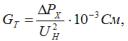
where ∆PX — in kW, UN — in kW.
The total active resistance of the windings RTotot is calculated by the formula:
If all three windings are designed for full power, then the active resistance of each of them is taken equal:
R1T = R2T = R3T = 0.5 RT total
If one of the secondary windings is designed for 67% of the power, then the resistances of the windings that can be loaded at 100% are taken equal to 0.5 RTotal. A coil which allows transmission of 67% of the power and whose cross-section is 67% of normal has a resistance 1.5 times more, i.e. 0.75 RTotot.
To determine the resistance of each of the beams, the equivalent circuits of the short-circuit voltage are presented as the sum of the relative voltage drops on the individual beams:
UK1-2% = UK1% + UK2%,
UK1-3% = UK1% + UK3%,
UK2-3% = UK2% + UK3%.
Solving this system of equations for UK1% and UK3%, we get:
UK1% = 0.5 (UK1-2% + UK1-3%-UK2-3%),
UK2% = UK1-2% + UK1%,
UK3% = UK1-3% + UK1%.
In practical calculations for one of the beams the voltage drop is usually zero or a small negative value. For this beam of the equivalent circuit, the inductive resistance is assumed to be zero, and for the remaining beams, the inductive reactances are found depending on the relative voltage drops by the formula: