Calculation of voltage drop networks
 Consumers of electrical energy operate normally when their terminals are supplied with the voltage for which the given electrical motor or device is designed. When electricity is transmitted through wires, part of the voltage is lost by the resistance of the wires, and as a result, at the end of the line, that is, at the consumer, the voltage is less than at the beginning of the line.
A reduction in consumer voltage compared to normal affects pantograph operation, whether it is for power or lighting loads. Therefore, when calculating any power line, voltage deviations should not exceed the permissible norms, networks selected from the current load and intended for heating, as a rule, are checked by voltage loss.
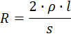
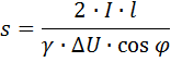
Voltage loss ΔU called the difference in voltage at the beginning and end of the line (section of the line). It is customary to specify ΔU in relative units — relative to the nominal voltage. Analytically, the voltage loss is determined by the formula:
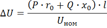
where P — active power, kW, Q — reactive power, kvar, resistance of ro — line, Ohm / km, xo — inductive resistance of line, Ohm / km, l — length of line, km, Unom — nominal voltage, kV .
The values of active and inductive resistance (Ohm / km) for overhead lines made with wire A-16 A-120 are given in the reference tables. The active resistance of 1 km of aluminum (class A) and steel-aluminum (class AC) conductors can also be determined by the formula:

where F is the cross-section of the aluminum wire or the cross-section of the aluminum part of the AC wire, mm2 (the conductivity of the steel part of the AC wire is not taken into account).
According to PUE («Rules for electrical installations»), for power networks the voltage deviation from normal should be no more than ± 5%, for electric lighting networks of industrial enterprises and public buildings — from +5 to — 2.5%, for residential electrical lighting networks buildings and outdoor lighting ± 5%. When calculating the networks, they proceed from the permissible voltage loss.
Taking into account the experience in the design and operation of electrical networks, the following permissible voltage losses are taken: for low voltage - from the buses of the transformer room to the most distant consumer - 6%, and this loss is distributed approximately as follows: from the station or step-down transformer substation to the entrance to the premises depending on the load density — from 3.5 to 5%, from the entrance to the most distant user — from 1 to 2.5%, for high-voltage networks during normal operation on cable networks — 6%, in overhead — 8%, in emergency mode of the network in cable networks — 10% and in aerial — 12%.
It is believed that three-phase three-wire lines with a voltage of 6-10 kV work with a uniform load, that is, each of the phases of such a line is loaded evenly. In low-voltage networks, due to the lighting load, it can be difficult to achieve a uniform distribution between the phases, which is why a 4-wire system with three-phase current 380/220 V is most often used there. In this system, electric motors are connected to linear wires, and lighting is distributed between line and neutral wires. In this way, the load of the three phases is equalized.
When calculating, you can use both the indicated powers and the values of the currents that correspond to these powers. In lines with a length of several kilometers, which in particular applies to lines with a voltage of 6-10 kV, it is necessary to take into account the influence of the inductive resistance of the wire on the voltage loss in the line.
For calculations, the inductive resistance of copper and aluminum wires can be assumed equal to 0.32-0.44 Ohm / km, and the lower value should be taken at small distances between the wires (500-600 mm) and cross sections of the wire over 95 mm2, and more at distances of 1000 mm and more and cross-sections 10-25 mm2.
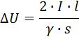
The voltage loss in each conductor of a three-phase line, taking into account the inductive resistance of the conductors, is calculated by the formula
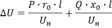
where the first term on the right is the active component and the second is the reactive component of the voltage loss.
The procedure for calculating the voltage loss of a power line with conductors of non-ferrous metals, taking into account the inductive resistance of the conductors, is as follows:
1. We set the average value of inductive resistance for aluminum or steel-aluminum wire to 0.35 Ohm / km.
2. We calculate the active and reactive loads P, Q.
3. Calculate the reactive (inductive) voltage loss
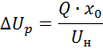
4. The allowable active voltage loss is defined as the difference between the specified network voltage loss and the reactive voltage loss:

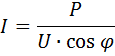
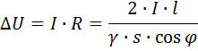
5. Determine the cross section of the wire s, mm2
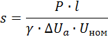
where γ Is the reciprocal of the specific resistance ( γ = 1 / ro — specific conductivity).
6. We choose the nearest standard value of s and find for it the active and inductive resistance at 1 km from the line (ro, NS).
7. Calculate the updated value voltage loss according to the formula.

The resulting value should not exceed the permissible voltage loss.If it turned out to be more acceptable, then you will have to take a wire with a larger (next) section and calculate it again.
For DC lines there is no inductive resistance and the general formulas given above are simplified.
Calculation of networks NS constant current voltage loss.
Let the power P, W be transmitted along a line of length l, mm, this power corresponds to the current

where U is the nominal voltage, V.
Wire resistance at both ends
where p is the specific resistance of the conductor, s is the cross section of the conductor, mm2.
Loss of line voltage
The last expression makes it possible to make a computational calculation of the voltage loss in an existing line when its load is known, or to choose the cross-section of the conductor for a given load

Calculation of single-phase AC networks for voltage losses.
If the load is purely active (lighting, heating devices, etc.), then the calculation does not differ from the above constant line calculation. If the load is mixed, i.e. the power factor differs from unity, then the calculation formulas take the form:
line voltage loss
and the required section of line conductor
For a distribution network with a voltage of 0.4 kV, which feeds process lines and other electrical receivers of wood or woodworking enterprises, its design scheme is drawn up and the voltage loss is calculated for individual sections. For the convenience of calculations in such cases, use special tables. Let's give an example of such a table, which shows the voltage losses in a three-phase overhead line with aluminum conductors with a voltage of 0.4 kV.
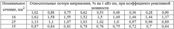
Voltage losses are determined by the following formula:

where ΔU—voltage loss, V, ΔUsection — value of relative losses,% per 1 kW • km, Ma — the product of the transmitted power P (kW) by the length of the line, kW • km.